ASTRAC Receivers
Summary: General Electric (GE) produced five ASTRAC micro-receivers.
Construction Details
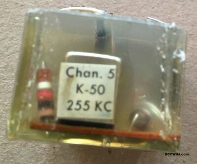
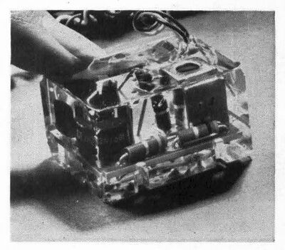
GE encapsulated ASTRAC Micro Receivers in a silicone rubber, measuring 1½ × 1½ × ¾ of an inch (38 × 38 × 19 mm). The receiver was usually located in the tender of a steam locomotive, and could be directly installed in a diesel locomotive. Power is supplied by two wires connected to the left and right wheels. A third wire connected to the motor.
Circuitry
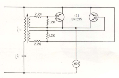
As the schematic shows, the ASTRAC receiver used a pair of 2N1595 silicon controlled rectifiers. The SCRs convert the AC voltage on the track to DC to control the motor. Control is by an RF signal which modulates the AC track signal.
Operation
A tuned circuit is formed by the tuneable inductor L and capacitor C, adjusted to react only to the frequency of that receiver. This LC resonant circuit provides voltage magnification. The selected frequency, such as 255kHz for the K-50 shown, is magnetically coupled to the gate and cathode of the SCRs. The tuned frequency would result in a voltage of approximately 2V being applied to the divider circuit formed by the 2.2kΩ and 1.2kΩ resistors. The resulting voltage (VGT) across the 1.2kΩ resistor would be enough to trigger the SCR. Other frequencies would not create enough current flow through the divider to trigger the SCR.
The SCR would need a minimum VGT of 200mV for reliable triggering, with the typical voltage being 700mV.
Direction was controlled by a switch on the transmitter, controlling the operation of the SCRs by sending the RF signal during the positive or negative half of the 60Hz track voltage. The RF is not a continuous carrier wave, it is only present for 180º of the track voltage's cycle.
Doing so switches one of the SCRs on, allowing current to flow to the motor. Which SCR is turned on determines the direction of the motor. As demonstrated by the schematic, the connections to the SCRs enable directional control.
Speed is determined by when the SCR is turned on. An SCR will switch off when the AC voltage crosses zero.
Specifications
The receiver is tuned at the factory for one of 5 channels at 100, 140, 180, 220 and 255 kHz. The K-50 shown is tuned for 255kHz
The receivers can handle up to 1.6A, with a 15A surge during the half cycle. They can handle a 48W load at 30V. Receivers are designed to operate from 6 to 30V, at 25 to 60Hz.
Track Power
Track power is supplied by a transformer, the transmitters were wired in parallel.
References
Notes
Hornby Zero 1 Locomotive Modules are often mistakenly identified as ASTRAC receivers. Zero 1 is a digital system, and lacks the IF can which is part of the tuned circuit. As ASTRAC is an analog command control system, it will have analog components such as the tuneable inductor (the IF can). Another clue is the silicone encapsulation, which Hornby did not use. Zero 1 modules also have pads or pins used to set their address.


