History of Digital Command Control
Summary: From the earliest days of Model Railroading, the idea of being able to operate trains in a prototypical manner was pursued. Advances included direct current power, solid state electronics enhancing operation with features like pulse power, and other innovations. The wiring would evolve to include complex block systems. With all these advances, the ability to control the locomotive, not the track, eluded everyone.
From the earliest days of Model Railroading, the idea of being able to operate trains in a prototypical manner was pursued. Advances included direct current power, solid state electronics enhancing operation with features like pulse power, and other innovations. The wiring would evolve to include complex block systems. With all these advances, the ability to control the locomotive, not the track, eluded everyone.
A series of innovations appeared over the years, beginning in the 1940s, but not until the appearance of low-cost microcontrollers did Digital Command Control appear. A number of proprietary command control systems were offered over the years, many had serious limitations, such as the number of channels, or expensive components. Limited support and expansion combined with lack of interchangeability hampered the adoption of command control.
The path to Digital Command Control began when the NMRA decided to investigate creating a standard for command control, to tame the confusion and fragmentation in the market. Early on, the members on the committee settled on digital as the preferred technology, instead of the prevailing analog systems on the market at the time.
Read on for more information on the systems and technologies that were the predecessors of today's NMRA Digital Command Control standard.
The History of Digital Command Control
History of how Digital Command Control came to be.
In this article the term channel used by command control systems would be equivalent to Digital Command Control's concept of addresses. Unlike DCC, the channels used by a command control system were often fixed, usually at time of manufacture. The Hornby Zero 1 system offered user programmed addresses, as it was a true digital system.
Many of the command control systems mentioned were analog in nature, using phase modulation, frequency modulation or audio tones to transmit commands to a decoder or receiver. For simplification, the term decoder refers to the electronics (the receiver) installed in the locomotive, that respond to signals from the control system. This is the reason behind the term channel, as a specific frequency is used to control a specific decoder tuned to that channel. Same idea as tuning your radio receiver to the station you want to listen to.
The terms Command Control, Carrier Control and Analog Command Control all have the same meaning in this context. Carrier Control was occasionally used to describe a system using a carrier signal to transmit control signals on the rails. These systems were analog in nature.
- Note
- All references to prices are in US dollars, and the date is in brackets. Many prices shown are from 1979. For comparison, $100 in 1979 is equivalent to about $290 today (by CPI, 2008). [1]
- Updated: $100 in 2013 is equivalent to $31.22 in 1979. Or, $100 in 1979 is approximately $320 in 2013 dollars.
- Updated: $100 (US) in 1979 is the equivalent of $375 in 2020.
- Updated: $100 (US) in 1979 is the equivalent of $460 in 2024.
The Early Systems
The idea of independent control of two locomotives goes back a long way. During the 1940s Lionel offered a system which employed a tuned circuit. A high frequency signal, created by an oscillator in the power pack, would control the direction of the locomotive. The locomotive would only react to the correct frequency, determined by the tuned circuit. Due to the nature of the electronics available in those days, the system was expensive and unreliable. Beginning in the late 1940s a new idea began to take hold, Progressive Cab Control, which was very complex to implement, and costly to construct and wire.
Advances in electronics, with the advent of cheaper, smaller and more reliable solid-state devices, made even more things possible. It would take about 30 years for command control systems to go from analog to digital in the form of Digital Command Control. The shift from the analog computer to the digital computer drove electronics to the present day's powerful but small microprocessors that make Digital Command Control possible.
Lionel Magic Electrol
In 1940, Lionel offered a new product called Magic Electrol, installed in a locomotive.
Inside every Lionel locomotive is a device called the E-Unit, that controlled direction. The E-Unit was described as a solenoid operated rotary sequence switch. The Magic Electrol controlled the E-unit. This allowed you to run two locomotives in opposite directions on the same track. Remember, Lionel used alternating current, so there was no way to flip the polarity. The E-Unit was originally developed by Ives, but lived on when Lionel took over Ives.
Instead of the usual method of controlling the E-Unit, where you cut track power to switch the E-Unit (forward-neutral-reverse-neutral) by pressing button 1, pressing button two (whistle) injected Direct Current onto the track that triggered the Magic Electrol unit.
After the US joined everyone else fighting the Second World War, Lionel ceased production of trains and Magic Electrol in 1942. But Lionel wasn't finished yet.
See a Lionel ad mentioning two trains on one track
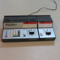
Lionel Electronic Control


The Lionel Electronic Train Control system consists of a one-watt transmitter and a number of small receivers mounted under or within a piece of rolling stock.
The system first appeared as the 4109WS Lionel Electronic Set in 1946. The set included a massive cast metal 671R Turbine (based on the Pennsylvania S2 Turbine locomotive) for motive power, tender with whistle, a boxcar, gondola, ore-dump car and caboose. This was the second major postwar innovation from Lionel, after the smoke unit introduced in 1945.
While the PRR built only one S2, Lionel built a considerable quantity of the model 671 locomotive. The R in the part number indicated Radio.
Each car could uncouple anywhere, with the press of a button. The set was a technical wonder, and a maintenance nightmare. Troublesome operations and a $75 price tag (over $1300 in 2024) resulted in the system being discontinued in 1949. A sizeable problem was dirty track and poor rail joints. To counter this, stainless steel was employed for track and axles.
The set was withdrawn in 1949, a victim of its high retail cost and poor sales. These sets do command a good price on the collector market, but are rarely seen in operation.
Read more about Lionel's Electronic Control on Google Books
Details
Transmitter
The transmitter was built around a 117N7GT vacuum tube that functions as an oscillator and a rectifier. Ten buttons controlled the operation of the oscillator, which produced RF signals from 230 to 350 kHz. This signal, measuring about 3 volts, was superimposed on the 60 Hz AC track power.
Receiver
Each receiver is a series tuned circuit, with a rectifier and a relay. The receiver is tuned to a specific frequency, which activates whistles, couplers or a dumping mechanism. Two types of receivers were made. One type was for the locomotive, the other for rolling stock. The tender would have two receivers installed, one to operate the whistle motor, the other to control the reversing unit. The type for rolling stock (of which there were four channels) operated the coupling mechanism, and in the case of the dump car, the dumping mechanism. To dump a load, the user simply held the button down for three to five seconds, which activated a thermal relay, which in turn controlled the unloading mechanism.
The channels were set up as 1/2 for the locomotives, 3 for the caboose, 4, boxcar, 5, gondola, 6/7 controlled the whistle motors, 8 was the dump car, with 9 and 10 being spares. The locomotives and caboose were fitted with RUB receivers, the boxcar was an RU, RUA for the gondola, RUD for the dump car, and the whistle was controlled by an RUC receiver.
The RUB and RUC were considered high frequency units, and the RU/RUA/RUD were low frequency units, channel 1 being the highest frequency. A complete RU-1 receiver was $5.00. Tuning was accomplished with a slug or plunger inserted in the input coil, which formed the primary of a transformer. A $2 tuning assembly completed the receiver.
Configuration
The configuration was like a command station/booster in two units. The variable transformer was connected to the Electronic Control Unit, and the ECU was then connected to the track. Lionel recommended feeders for long runs of track. The rolling stock was fitted with stainless steel axles to improve conductivity.
The vacuum tube used in the transmitter functioned both as an oscillator, and a rectifier. A 117N7GT is a tube with a 117 V filament (no filament transformer needed). It combined a diode and a pentode in the same package, the maximum voltage on the plate and screen was 117 V, and it was classed as a Class A Amplifier Half Wave Rectifier. Its power output was 1.2 W maximum. Lionel chose this device to simplify the design and keep the cost down.
The Fifties
EDCO
Model Railroading by Radio Control
In the early 1950s a radio control system was advertised by EDCO Products. The system did not require a radio operator licence. It first appeared in 1952. It seems to have promptly disappeared, after only one advertisement published in February.
It was available as a complete unit, kits, and individual parts so you could construct your own system. The plans were available for $1.95, which would be credited to your order if you bought $20 or more in parts.
The control system used a single vacuum tube transmitter with ten channels, small receivers (which didn't require a tube) that could be fitted to locomotives or rolling stock.
It featured constant voltage on the track, the control was on the train. EDCO stated you could control several trains on one track, uncouple, smoothly accelerate/decelerate, start and stop, and even reverse with no effect on another train operating on the same track.
The Sixties

The Sixties brought a lot of change, and that included model railroading. Command Control, or as it was often called, Carrier Control would benefit from the revolution set off by the transistor and other semiconductor devices. Carrier Control indicates the control signals reach the receiver by wire (such as the track), whereas Radio Control indicates wireless transmission of the signals. In either case, a carrier, such as an audio frequency tone or a radio signal, carries the instructions to the receiver.
Linn Westcott made a number of observations in his December 1962 editorial for Model Railroader. One observation stated that many carrier control systems were created by those who recently joined the hobby, who happened to be electrical or electronic engineers. They had enthusiasm but lacked in-depth knowledge about the hobby and what it needed. The same effect was seen in transistor throttles. There was no real demand for carrier control technologies, as cab control had evolved and was well understood.
Westcott presented a number of features he felt were necessary and should be considered by those planning to design a carrier control system.
- Receivers should be as compact as possible so they would fit into the confined space of many locomotive bodies;
- Ability to move at both slow and high speeds;
- Locomotives should not interfere with each other during operations;
- No EMI/RFI which would cause problems with radios or televisions;
- Tuning should be possible without special tools or instruments, preferably while the locomotive is still on the track;
- Your track plan and wiring style should have no detrimental effect on performance;
- Compatibility with Direct Current, such as using DC for the motor, signalling, constant lighting, and reversal of polarity shouldn't cause problems.
Roundel Track Master
The Roundel Track Master appeared in an advertisement in the September 1962 issue of Model Railroader (MR). The Track Master claimed the capability to control several locomotives. The Track Master II also professed to eliminate many wiring issues such as reversing loops.
Outside of a few samples, the system seems to have never made it past the prototype stage, and it was never sold commercially.
A preproduction sample of the Track Master was reviewed by MR in March 1963. A control unit was provided potted into a boxcar body meant to be placed trackside. The receiver was sizeable but claimed to fit into a diesel B unit, large steam locomotive tender, or a boxcar. A third unit, the Track Master III was mentioned as well. In the October 1963 MR it was noted that the Roundel system never reached the market and only two units went into operation on a layout.
The review says its “chief purpose” is to deal with reverse loops and wyes. The receiver had two bridge rectifiers fed by both trucks, with each truck getting power from both rails. This made the trucks independent from each other. Their design included a set of freight trucks for this or you could make your equipment’s trucks work in a similar fashion. A short section of dead track was placed in the return loop or wye. While one truck was on the dead spot, the other truck continued to provide power. This eliminated the need to reverse power to the rails.
Automatic Simultaneous Train Controls
General Electric's ASTRAC

The first command control system on the market since the Lionel Electronic Control System. Designed and manufactured by General Electric.
See the main article on Automatic Simultaneous Train Controls for more information
Both ASTRAC and Alphatronics employed Frequency Domain Multiplexing for their channels. This limited the number of available channels. Both systems suffered from issues with heat causing the frequency to shift and resulting loss of control of your train, and possibly gaining control of another. The ASTRAC decoders were also rather large and hard to install in typical HO Scale equipment.
Alphatronics
An improved ten channel version of the five channel ASTRAC system offered by GE, developed and manufactured by Alphatronics.
Featuring 10 channels, compatible with ASTRAC, and additional channels were available by special order. A basic system cost about $300, (almost $2200 in 2023) and decoders were $40 to $50 (in 1979). Track voltage was about 19 Volts. Alphatronics began manufacturing a receiver compatible with ASTRAC transmitters in 1972, and announced a compatible transmitter in mid 1972.
It was described as a ten channel, AC carrier wave, frequency-controlled system.
Alphatronics offered three configurations: A single fixed channel transmitter, a transmitter which allowed selection of any one channel using buttons, and a transmitter with a rotary switch to select one of ten channels. The transmitters could be ordered with tethered throttles. The throttles could be plugged in at remote stations. When the throttle was disconnected from the system, the train would stop. The throttles were simple units with a speed control and reversing switch.
Two receivers were offered. The A3 was a single unit about 3/8 x 1/2 x 1.5", and the A4, which was split in two parts for fitting into a tight space. The receivers were often installed in a dummy unit. The A3 had enough capacity to handle up to three locomotives in a consist. The decoders were three wire types. The A3 retailed for $35.75, the A4 was $50.
The Alphatronics system appeared in 1972, and was on the market until 1981. The Alphatronics receivers also used a single TRAIC instead of the two SCRs used by GE's ASTRAC receivers.
The Seventies and Eighties
The era that spanned the early 1970s to 1989 spawned a number of command control systems. In the beginning they were analog, but early on systems using digital technology began to appear.
Jouef
According to an answer published in the MR Clinic, August 1972 Model Railroader, Jouef of France made a very similar system to ASTRAC, which was never exported to North America.
Details from 1968 indicate it was a carrier control system, using an AC waveform on the track, tension (French for voltage) was 14V. Initially offering 4 channels, with the possibility of more in the future. The receivers were compact at 0.4" x 0.5" x .8".
Jouef-Matic 76 system
The first generation of the system, with only eight receivers and two transmitters. Each transmitter may alternatively control four receivers, and it will take until 1976/1977 for the eight receivers to become truly independent. Receiver and transmitter prices were dissuasive and relatively closed to the price of a locomotive.
Philips
Philips may also have demonstrated a similar system but details are very scarce.
From 1974 to 1976 the series EH (Elektronik Hobby), electronic train control (EZR) and an electronic block track system (EBS). [2]
EZR
Analog multi-train control system in which up to 8 locomotives are controlled by different sound frequencies. Each locomotive had its own control unit and receiver.
There were versions for AC and DC operation.
EBS
- EH 3050: Block point module
- EH 3051: Rule Building Block
- EH 3052: Signal Block
The feature of the Philips EBS is electronic control without relays and switching tracks. As a result, the wiring is reduced. A minimal system consists of a single EH 3050 module. This allows an oval (or other closed track figure) can be divided into 3 blocks. This enables automatic and collision-free control of two moving trains. In the EH 3050 there is soft start and braking within the block sections. Several EH 3050 can be plugged together.
With the EH 3051 control block, an additional route can be planned. Together with an EH 3050, this results in 4 blocks controlling 3 trains. Sections with the EH 3051 have their own speed controller and direction switch. This is recommended in station areas with trains ranked within the EES.
The optional EH 3052 signal module enables 4 block signals according to the switching state of the EBS.
Digitrack 1600
The Digitrack 1600 offered 16 channels. Manufactured by Electro-Plex Inc., of Urbana Ohio, USA, it allowed selection of channels by changing a plug. First mention was in 1972. A basic four channel starter set sold for $339.95. Additional channels available at extra cost. The Digitrack 1600 system went out of production in 1975.
Digitrack was the first command control system to use digital control signals superimposed on a DC voltage (time division multiplexing), but the cost and complexity of the system doomed it. The equivalent price in 2023 would be in excess of $2500.
The Digitrack 1600 Master Power Pack transmitted 16 pulses sequentially, one for each receiver. The pulse was nominally 250uS (microseconds), and could be as long as 500uS. Using timing, where the pulse began and ended in relation to a fixed point in time determined direction and speed. A sync pulse locked the timing of the receiver to that of the transmitter, allowing it to count pulses and determine the instruction intended for the receiver. The difference between the clock and the pulse determined speed and direction. Instruction pulses were transmitted 100 times a second.
Russ Larson reviewed the Digitrack 1600, demonstrated by creators Balmer and Robbins, in operation on Linn Westcott's Sunset Railway and Navigation Co. in the August 1972 Model Railroader (of which he was the editor), and was impressed with system's performance. This would lead to the CTC-16 project later.
Carrier
Track voltage was a nominal 13.5VDC, the pulses were 4VDC.
If viewed on a scope, the waveform would show a DC voltage with sixteen 4V pulses riding on the track voltage, as produced by the Master Power Pack. Think of it as a 4VDC pulse with an 11VDC offset. There would be the sixteen pulses, then a period of low voltage (~11VDC) before the pulses began repeating, forming a synchronization pulse. The receiver module counted the pulses until it arrived at the one it was waiting for, which it then acted upon. The duration of the pulse, and its relation in time (phase) determined speed and direction.
This also gave the user the ability to use constant lighting, as the track was energized at all times.
System Configuration
The Digitrack 1600 was a three-piece system: The master power pack, a control box (throttle) and the receiver. Additional auxiliary power supplies could be connected to the master power pack to increase the system's current capacity to eighteen amps.
The master power pack was designed to supply 13.5VDC (nominal) to the track, at 4.5Amps. The receivers could output from zero to 12VDC to the motor. Current consumption was 100mA, maximum motor current one amp.
The address the throttle controlled by determined by which position it was plugged into on the master power pack. Sixteen plugs (or positions) were available, one per channel/address, using four position connectors similar to those used in computers to connect power to hard, floppy, and optical drives (prior to the arrival of the newer SATA peripherals).
Receivers
Receivers for the Digitrack 1600 measured about ¾ × 1 × 1¾ quarter inches. They could fit in many HO scale locomotives, or be installed in a dummy or tender if needed. Dual motored HO locomotives could be converted if the current draw was less than one amp in total. (The 1A rating was a nominal value, up to three amps peak was possible). The decoders were not powerful enough to handle O Scale applications, it is unknown if that ever changed. Electro-Plex did say they planned a 5A version for O Scale applications.
Due to size and the constraints of the technology, N scale was not supported. Future plans included the possibility of smaller receivers.
It was also possible to bypass the receiver using a plug or switch to allow operation on a Direct Current layout. Unlike Digital Command Control, a direct current locomotive not equipped with a Digitrack receiver would react to the constant track voltage by accelerating at full speed.
Double Heading (or consisting) was possible. The locomotives could be on the same, or different channels.
Miscellaneous Details
Reverse loops required a switch to swap track polarity, otherwise a short would occur. Flipping the polarity during operation had no effect on the motion of the train, as the receiver was not sensitive to polarity changes.
Re–Invention as CTC-16
Model Railroader purchased the publication rights and planned a series of articles on constructing and operating a Digitrack system. Upon review, it was determined to be too expensive for a do-it-yourself project, and the Digitrack 1600 evolved into the CTC-16 system which appeared in the December 1979 issue of MR. Digitrack is compatible with CTC-16, which used more advanced components which were available at the time.
Another device called "DigiTrack" was unrelated, as it was a handheld throttle. Kato also called their system Kato Digitrack.
ARI-TRONICS
This carrier control system appears to have been another planned but never truly realized product from ARI-TRONICS of Scottsdale Arizona. Although advertised for about a year, there is little known about the system outside of what was presented in the ads.
Advertisements for the unit appeared in mid-1971.
ARI-TRONICS offered the ability to independently control the speed and direction of up to five locomotives on the same track. The system was a solid-state design, available in kit form or fully assembled, with the power supply included. It was described as a miniature frequency control unit for HO locomotives.
Later a lower cost two engine control system was offered in an easy to build kit, for $24.95, with support for N scale as well.
ME-80
(Mehrzug Elecktronic 80 / Multi-train Electronic 80)
The ME-80 was made by A Fienwerktechnik in West Germany, and sold in the US by Janssen Enterprises.
An advertisement for the system appeared in the June 1976 issue of Model Railroader. It did not contain many details, but it did claim the ability to control up to six locomotives without the need for a block system, 'forwards, backwards, fast and slow' the ad stated. The front panel of the main unit pictured was labeled in German. It bore the appearance of a piece of high-tech electronic test equipment with it's aluminum face, blue cabinet and a wire stand which raised the front of the unit.
The main unit had six slide switches, which allowed the user to set the hand-held unit's channel. The front panel had the selector switches, indicator lamps, fuse holders and six DIN plugs for the hand-held interface. There were also the "Telex Crystal" (sound accessories), receiver crystals and rectifiers available to be installed in your motive power. Like many command control systems, it put constant power to the track and claimed to eliminate a lot of wiring.
Each channel used a pair of frequencies, one for forward and the second one for reverse operation, which controlled the receiver. A steam sound generator was also available which could add the chuff and whistle sounds.
The suggested price was $925 (in 1976, or $4977 today (2023)).
CTC-16
See the main article, CTC-16.
A 16-channel system, superseded by the RailCommand system. Appeared in 1979 when Model Railroader magazine published a series of CTC-16 articles as a do-it-yourself project. Based on the Digitrack 1600, with simpler construction using newer integrated circuits available at the time.
CVP Products was one of the suppliers of CTC-16 systems.
CTC-16e
Another CTC-16 compatible system called CTC-16e appeared in 1984. Again, designed for people to build themselves.
The CTC-16e featured a dedicated throttle, or a selectable channel throttle which used what was called the T/BUS.
The dedicated throttle was built for a specific channel. The T/BUS throttle featured 16 channels, with a three-wire connection to the system bus. T/BUS allowed channels 0 to F, which were digitally transmitted to the command station. The T/BUS throttle featured momentum, braking and throttle memory.
CTC-64
Another evolution of the CTC-16 concept, with 64 channels.
DIGI-PAC 316
The DIGI-PAC 316 was a commercial version of the CTC-16, manufactured by Mann-Made Products. It appeared in 1982, offering 16 channels. It claimed to work using Digital Proportional electronics, despite the fact it was an analog command control system based on the CTC-16 project published in Model Railroader, with revised circuitry and updated parts. The receivers were smaller as well.
Prices were as follows (for 1982): Power station, $61.50, control station $105.90, throttle with a knob was $19.95, or with pushbuttons, $17.85. The receivers were $39.50, channel selector plugs $5.95 each, and selector receptacles $4.95. The basic start set consisted of the power station, transmitter, two throttles and two receivers. Today that would cost more than $900 (2023). An additional extra cost third party 24V 4A transformer was required to provide power.
A selector receptacle was needed at every position you wanted a throttle to be plugged in. This was then wired to the control station. If you wanted to use all 16 channels, a 19-conductor wire would be needed. Wiring the receptacles was one of the most time-consuming parts of the entire installation. The selector plug could be connected to any throttle and then plugged into a receptacle.
The system allowed for the optional "Plug Around" operation, which was their name for memory operation. The speed and direction would be maintained, but over time the train would slow to a stop if the throttle was not plugged in. An optional throttle used push buttons for one handed operation. It was also possible to add radio operation for $36 in addition to the cost of the throttle.
The receivers were designed to fit HO equipment without cutting. They were 11/16" wide, 4 9/16" long, and about 3/8" in height, for the diesel (D1) version, and were capable of 1A surge and half an amp continuous. For Steam, the S1 was 1⅛ × 2¾ × ¼", or the S2 at 1½ × 2⅜ × ½", and offered the same current capabilities as the D1. Mann-Made promised receivers for N scale.
W. Alan McClelland installed the DIGI-PAC 316 system on his Virginian and Ohio railroad, previously he had employed GE's ASTRAC system beginning in 1963.
In 1984 the Dash II version was released, which allowed up to 32 channels. It was compatible via upgrade with the CTC-16, but not the CTC-16e cabs.
For a review of the DIGI-PAC 316 see the September 1982 issue of Model Railroader. The same issue also features the DIGI-PAK 316 being installed on a project layout. It is also mentioned in the November issue's article on the V&O.
CTC–80
Computer Throttle Control 80.

A later computer enhanced version of the CTC-16 was the CTC-80. It was the third generation of the Digitack 1600, using a Z-80 microprocessor in place of the analog processor in the CTC-16. Manufactured by Keeler Rail Specialities. It appeared in early 1988.
Required a personal (micro) computer to control the system. Compatible computers were the Apple II, the IBM PC, or the Radio Shack Model III, which interfaced to the CTC-80 via the serial port.
The system could operate in 16, 32, or 64 channel modes, for up to 64 locomotives under its control, with the ability for 16 throttles to be connected to the system. Channels 17 to 32 were reserved for computer throttles. The CTC–80 receiver offered 64 channels, compared to the 16 of the CTC-16 receivers.
The command station was $400 (more than $1000 in 2023), a throttle $75, and receivers were $50. A power station control card was $30. The power station was only available as a kit, or the power station control card could be used to upgrade an existing CTC-16 system. The full setup was only required if there was no existing command control system on the layout, otherwise upgrading a CTC-16 system was possible with fewer components.
Computer Software
BLOCKHEAD CTC16-80

Announced by Custom Control Systems in 1981, the Blockhead CTC16–80 software would allow the dispatcher to control the model railroad from a computer, compatible with the CTC-16. The system would include software and hardware, with a design manual. Originally written for the Radio Shack/Tandy TRS-80 computer, software was planned to allow other computers to be used. As a minimum, the system could control routes, cab signals, trackside signals and hump yards.
It is not known if this software package made it past the announcement stage.
Dynatrol
Power Systems Inc., introduced Dynatrol in 1978, now sold as Classic Dynatrol. Dynatrol is an 18-channel system (originally only 15 channels were offered), using a track voltage of 13.5VDC, and a frequency shift reversing system. It used audio tones to transmit commands. Additional channels were planned to control sound effects. It was one of the more sophisticated command control systems on the market.
One feature was walk around throttle with a memory feature. The plug-in channel selection made it very versatile, as well the ability to reset the circuit breaker from the handheld throttle.
Dynatrol featured three different throttles
- The Full Function cab offered adjustable momentum, a rotary mainline brake controller and push button brake plus the throttle and direction controls
- The mid-level cabs offered two independent direction selectors (MU-2) or three (MU-3) which allowed the operator to create and control a multiple unit lash-up
- The Direct Function cab was a simple throttle with forward/reverse control
Dynatrol uses a supersonic carrier, with modulation of the duty cycle to transmit information to a pre-programmed receiver in the locomotive. Each throttle has its own oscillator and modulator, controlled by the throttle and brake controls. The carrier frequency is determined by a precision resistor installed in a small plug, called a channel plug. Reversing the locomotive is accomplished by phase shifting the carrier slightly. Receivers were available in various sizes that could fit N scale and larger locomotives. Multiple power supplies ($55 in 1979) and blocks were needed to reach the 15-locomotive capacity of the system.
Channels were selected using key plugs. Momentum and braking effects were also available.
Dynatrol suffered from the same issues as other carrier control systems. As the channel frequency increased, reliability decreased, especially as the receiver moved further away from the transmitter. Reliable signal strength was difficult to maintain at all points on the layout. Wiring had be robust, with minimal connections to avoid attenuating the carrier signal. Feeders were also very important to maintain signal reliability. The receivers were also rather large, imposing limitations on what vehicles they could be installed in.
The system has been on the market since 1978. Dynatrol and Onboard were among the most popular command control systems in use. Those two were among the more costly systems on the market, with a Dynatrol start set with 2 Full Function cabs and the base control unit costing $285 2023: $1400), plus the required power supply and filter capacitor costing an additional $50. Full Function cabs cost $15 more. Receivers cost $50 to $70 each, depending on their current rating. A basic direct or non-momentum cab cost about $65, and a full function cab was $75.
PSI was also working on a sound unit for the system in 1982.
EMS
EMS was manufactured by Trix in Germany and sold by Walthers in North America. It used a 9.5 kHz carrier to control a locomotive with a receiver. It worked with an existing DC control system, allowing both DC (analog) and EMS equipped locos on the same track. A controller and receiver rated at 850 mA would have cost over $100 in 1979 (more than $480 in 2023).
This system would be considered an AC/DC system. A high frequency AC signal was superimposed on the DC applied to the rails and the locomotive equipped with the receiver would act on the signal. This allowed independent control as the standard DC locomotive just ignored the AC voltage.
One locomotive was controlled by the power pack, the other by the EMS system, allowing the two to operate independently of each other. The EMS controller was a single knob for speed and direction. Additional parts made it possible to bridge gaps in the track work, enabling the EMS equipped locomotive to travel independent of the block boundaries by passing the AC signal while blocking the DC voltage.
A receiver was $35, and the EMS controller $75.
ONBOARD Locomotive Sound and Control
The ONBOARD Locomotive Sound and Control system, by Keller Engineering, offered 20 (originally ten) channels, with a constant 12VDC on the track. It used audio tones to control the locomotives. A base system was about $376 (1986, 2023: $1027). Wireless throttles were also available. The ONBOARD system claimed to eliminate the need for control panels and block wiring.
It offered steam locomotive exhaust sounds, bell and whistle. For Diesels, it featured a variable prime mover RPM, exhaust, bell and six chime air horn sounds, plus constant lighting. An optional feature was directional lighting.
A typical starter set came with a 5A power supply, a 16-channel handheld controller, two 1A motor controllers and the manual. The handhelds generated both throttle and sound commands with crystal-controlled oscillators. They used a keypad, with keys for the sound effects, throttle up and down. Bringing the locomotive to a stop and holding the throttle key reversed the direction. The keys were colour coded, and each handheld could control two locomotives. Signals from the throttles were fed to a mixer, each mixer could support four channels generated by two handhelds.
The ONBOARD system used a pair of phase locked loops (PLL) to control acceleration and deceleration, with resistors selected to determine the frequency of each PLL. Depending on the temperature coefficient of the resistors used, the frequency would vary with temperature. Which could result in a throttle which was very sensitive to temperature changes.
The receivers were called throttles and were installed in a locomotive or dummy unit. The ONBOARD system claimed to eliminate the need for control panels and block wiring.
Another accessory was a signalling system, for use with lights or semaphores.
Basic ONBOARD System
Keller also offered a basic OnBoard system. This system is not as well-known as most of the marketing effort went to the ONBOARD sound system. The throttles were push button only, with an optional throttle featuring more tactile feedback. The receivers were small enough to fit into an N Scale boxcar.
The throttles also featured the ability to control wo locomotives, allowing MU operation regardless of the direction they faced.
The basic OnBoard system sold for $264 (1982, $840 in 2023), without a power supply. The one-amp receiver retailed for $39. Sound receivers sold for an additional $103 per locomotive. A basic receiver's cost in 2021 would have been about $110, the sound unit $300.
Technical Details
- Motor controllers available in 500mA, 1, 2, and 4A versions, also controllers for garden railways. Built in memory, with pure DC out at full speed.
- Steam Sound unit
- Optical exhaust sync (or magnetic for outdoor use), automatic 2 stroke air pump, adjustable 6 chime whistle, bell.
- Diesel Sound unit
- Exhaust controlled by motor voltage. Selectable 6 chime air horn, bell. The synthesizer as Onboard called it was usually installed in a dummy, and powered by a rechargeable battery maintained by the track power.
- Reverb unit
- Up to 100mSec of delay, with controllable echo repetition.
All sound units featured a 1 W amplifier.
Radio
A radio adapter was also available, using a Futaba unit, which was directly usable in large locomotives.
You can use Onboard sound modules with DCC. See the Digitrax Knowledge Base for details. (Operating Keller SU1990 Sound Unit with Digitrax Decoders.)
Keller Engineering closed in 1994, and its founder, Bob Keller, passed away in 2007. While the ONBOARD system has been out of production for more than 20 years, it is still in use today. Unfortunately, most of the documentation was destroyed when the business closed.
MRC Protrac
Sometimes called the "ProTrac R/C 1".
Protrac was a system announced in 1979 by the Model Rectifier Corp. The Protrac R/C 1 System 7000 controlled two locomotives, only one was decoder equipped. It was an AC/DC hybrid similar in concept to the EMS system. According to a review in Model Railroader (November 1979), it didn't appear to be radio based. The Protrac 7000 featured a dual throttle console, which looked similar to an R/C unit for model airplanes.
The system works by using throttle A (analog) to control the first locomotive with a receiver using "Carrier Control" was installed in the second locomotive, controlled by AC signals (in the range of 8kHz) on the rails, using throttle B. The usual block control method was needed to run multiple trains.
The receiver would fit most HO locomotives but was too large for N scale. The better option was to install the receiver in a dummy as it needed enough room to warrant removing some mass from the locomotive frame.
A promised R/C 2 System 9000 featured eight channels with radio control for wireless operation. The Protrac system was not compatible with any sound systems that used track current to power them. At the time, the only compatible sound system was the battery powered Train Miniatures system. Other brands, such as the PFM (Pacific Fast Mail), Lambert Associates and Modeltronics sound systems were not compatible with this system.
MRC quoted prices of about $100, and $150. (1979)
Rail-Command 816
An eight-channel digital signal system using a constant 12VDC on the track. Manufactured by Integrated Systems.
A single tethered cab which could control one locomotive sold for $14. A dual channel unit was $20. The locomotive would continue to run while its cab is unplugged. The throttle featured a single speed/direction knob, and a switch to enable momentum/braking effects. There was a brake trim control to allow adjustments for the characteristics of your locomotive.
Another part of the system is the throttle-transmitter unit. It was the power supply and signal generation system. Channels were selected by plugging a cab into one of the eight jacks on the unit. Additional power boosters were available to increase the power available. The 4-amp throttle-transmitter sold for $75, and the accessory 8A booster was $50. Receivers cost about $25 each. To allow more flexibility, remote jack panels were offered for $11, as well as bulk cable to connect it to the system.
Stancal RFPT
The Regulated speed Full wave Positionable Throttle was a nine-channel system using a constant 12VAC track voltage, with high frequency signals to control the locomotive. Handheld throttles (Throttle Control Unit or TCU) were $25 for a single channel or $50 for three channels. The Engine Control Units sold for about $53 (1979). A basic system (a triple TCU and three ECUs) was about $200.
The early units offered only six fixed channels. Future systems promised nine channels.
The system was built around model aircraft radio control components. The ECU consisted of a servo motor driving a gearbox, which in turn drove a potentiometer controlling a transistorized throttle. The ECU also rectified the 12VAC to Direct Current for the motor. It was noisy during speed changes due to the servo its gear train.
The throttles featured rocker switches to control speed and direction. The throttles could only send one command at a time. Dirty track could result in loss of control.
Salota 5300
The Salota 5300 was a West German system imported into North America. It used a constant track voltage of 16-18VDC, and offered 5 channels. The Salota Power Deck/Control Transmitter featured 5 knobs which controlled the speed and direction of the 5 channels. It used a constant voltage of 16 to 18 VDC on the track. The Salota 5300 appeared on the market in the late 1970s.
It was suited to any scale that used 12 V motors. The control system measured 9.25 by 9.25 by 3 inches. Receivers measured 40 x 25 x 17 mm.
The system was advertised for $300 (including 2 receivers), and receivers were $40 each in 1979.
Airfix Multiple Train Control System (MTC)
An analog system introduced in 1979 by Airfix. Could control up to 16 locomotives, with a maximum of 4 at a time. The presence of an IF can on the receiver indicates it is a tuned carrier control system.
The main unit consisted of a console with sixteen selector switches to select one of four channels (A, B, C & D), with trays for the hand-held throttles (up to 4 could be accommodated). The base unit was capable of transmitting on all sixteen channels simultaneously. The system did suffer from frequency drift, and crosstalk between adjacent channels was common. The track was energized with 20VAC at all times, which could cause pitting of the locomotive's wheels. Receivers were sold labelled as one of four groups, and part of install involved tuning to the desired channel (one of 4 in that group) by adjusting the tuning slug in the IF can.
Prices were UKP 85.00 for the main unit, with two handhelds and two receivers. Additional handhelds were UKP 9.95 each and receivers were UKP 4.95 each. (In US dollars the prices would be approximately $179, $21, and $11).
A simpler two controller version was advertised but never sold in 1981. Very basic with only two handhelds, and no channel selection. Airfix entered receivership at the time, which effectively ended the product and any future versions.
More info and pictures: Airfix Railway System
FMZ Fleischmann Multi Train
- Fleischmann Mehrzugsteuerung
Introduced in 1987 by Fleischmann. The system is meant for use with two rail systems.
In FMZ multiple positive or negative pulses follow each other. To the individual pulses still distinguishable there is a short zero volt pause, the so-called "Takt Pause". The pulses are 28 microseconds, the cycle breaks are four microseconds. A positive pulse is seen as a logical "1", a negative pulse is "0".
The bits are always grouped into 8 pieces within a byte. To ensure that the message is understood the first byte is repeated but inverted. This signalling method has the additional benefit that the average voltage of the signal is zero.
This will allow an analog locomotive. An analog locomotive can now be controlled by adding a DC voltage on the track. Fleischmann planned from the beginning to allow analog locomotive operation.
Hornby Zero1

A true digital system. Introduced in 1979 by UK manufacturer Hornby, and to the US in 1980 and Canada in 1981. It was a digital system based around a Texas Instruments TMS1000, a four-bit microcontroller able to address and control up to 16 locomotives.
For more information, see the main article: Hornby Zero 1.
Hornby Zero 1 master and slave units
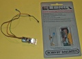
Locomotive Module R.955
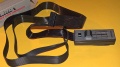
Handheld Slave Controller for the Zero 1


- The most popular of all the command control systems in use by the mid 1980s (Model Railroader reader surveys). Components can still be found for sale on the internet. Questions often appear on on-line forums asking about using a system someone got, or wondering if it is compatible with DCC.
Due to financial difficulties and the reorganization of Hornby's parent company, development of the Zero1 was frozen, with no new developments or advancements. Many people mistakenly identify a Zero 1 locomotive module as an ASTRAC micro-receiver. The ASTRAC receiver is an analog device potted in silicone rubber. It bears little resemblance (physically and electrically) to the Hornby Zero 1 module.
MTR Services
Offered their Power Grid Systems command control system, which was compatible with the Zero 1 system, in 1996.
ZTC Controls

ZTC Controls in the UK still support the Zero1 system and have made improvements to it.
ZTC also make DCC decoders that can be programmed to work with a Zero 1 system, and their controllers have a mode that enables control of a Zero 1 equipped locomotive.
One of the founders of ZTC was employed by Hornby as part of the Zero1 development team.
ZIMO
ZIMO began offering a digital command control system ZIMO Digital (BGT-1, FP-2, FZE-2) in 1979, around the same time as Hornby's Zero 1. The major difference was the ZIMO system could control 99 trains and offered 16 speed steps. (Zero 1 only offered 14). Development began in 1977, with the product coming to market in 1979.
Zimo would continue to innovate, with computer controls and CTC capabilities. Zimo began selling NMRA compliant DCC systems in 1994. Zimo still offers their HLU signalling and automation system developed in the mid–80s today
Zimo Digital Signal Format
Zimo's digital signal is completely different from that found in the other digital systems. On the track is a DC power supply, superimposed thereon is the digital information in the form of short pulses of alternating voltage. The voltage is variable between 15 and 22V. The frequency of the alternating voltage is about 8.5 kHz, with the pulses having three different lengths. A pulse of 25 periods, the synchronization pulse, indicates that there is a new message beginning. The message itself consists of pulses of 5 periods (logical "0") and 10 periods (logical "1").
Between two synchronization pulses there are always 16 data pulses. The first 8 are the address bits. With these 8 bits 255 different addresses can be formed.
After the address follow 4 data bits for various functions, successively MZRL. M is for switching operations, Z is an additional function, R is direction, and L is the light. The next 4 bits contain the speed information, which allows for 16 speed steps.
Zimo Digital also has a special brake module for a stop section. If the signal is red momentary power interruptions are caused this module at the end of each synchronization pulse. These short interruptions cause the decoder to slow the locomotive to a stop with the set delay. All functions remain operable for the stationary locomotive.
Kato Digital
Also called Kato Digitrack The Kato Digital system appeared in the late 1980s and was discontinued a few years later. Advertisements for a forthcoming Command Control System by Kato appeared in late 1986. It featured up to 100 addresses available, a primitive sound function, and capability to control switches, either with a controller or a computer via RS232 (serial port).
Capable of controlling up to 16 locomotives out of 100, with eight under simultaneous control. Up to 256 turnouts or other accessories. A square wave of +/-18V was present on the track, with the digital signals being present for the first 2mS of an 11mS pulse.
The system was proprietary, and decoders would only fit an HO locomotive (due to their size).
Basic system:
- 4-501 Main Controller $420
- 4-502 Subcontroller $160
- 4-503 Switch Controller $160
- 4-504 Power Supply $175
The subcontrollers, up to three of them, plugged into the main controller, as did up to 16 switch controllers. With the addition of three subcontrollers control of eight trains at the same time was possible.
Locomotive receivers ranged from $70 to $80. Switch controllers cost $70, and the sound module was $7. One receiver was made specifically for a KATO JNR prototype locomotive, the other two (a 1A and 4A) were general purpose. The receivers were shown beside a ruler, ranging from 20 to 90mm in length.
KATO dropped the system in 1992.
Marklin Digital
Marklin Digital appeared on the market in 1984. This system was designed for use with Marklin's line of Alternating Current (three rail) HO trains. Developed by Lenz for Marklin. Uses Motorola parts, hence the different mode and compatibility settings. It is the system that uses the Motorola format for sending commands. It is not compatible with DCC, but some manufacturers support the Motorola format in their command stations. The original format supported up to 80 addresses. Marklin and Arnold would market similar systems based on the Lenz design, Arnold would later exit the agreement due to patent/licence issues.
Two Marklin systems were sold: Digital~ for their three rail AC products, and Digital= for two rail Direct Current.
Marklin would also introduce another digital system developed by a third party for use with their DC product line.
Although Marklin Digital sold well in Europe, in North America it did not fare as well. The system was first demonstrated in 1979, going on sale in Europe in 1984 and in North America in 1986. (Marklin Website)
Trix Selectrix
A digital system that appeared in 1982, reintroduced in 1987 as "Selectrix". Very small decoders, but more expensive (single supplier) than DCC. Trix is now part of Marklin, and the brand is used to identify their Direct Current (two rail) products.
PMP-112
Not much is known about this system. It appears to have been another do-it-yourself system, published in 1988 by Model Railroad Craftsman. There were a number of articles about constructing it, including a Diesel Sound Module. It was capable of controlling up to 112 locomotives and was a derivative of the CTC-16 system.
Sound Systems
While not really command control or DCC, sound systems began to appear as well. Some were simple, others complex.
Lambert Associates
Imported by Lambert Associates. Provided chuffing sound, easily fitted to an HO scale steam locomotive. Device measured 0.47 high 0.55 wide and 0.25” long. A small capacitor was also part of the package. It was mounted using included tape, and small speaker completed the package. Also required was a chuff cam, but alternate methods were possible to activate the chuff sound.
The entire package would be installed in the tender. The booster unit provided more volume and a deeper bass.
Ready to install steam unit: $32.95, booster: $12.99
Pacific Fast Mail
PFM was an importer of brass locomotives. Many of their catalogs featured photographs by John Allen taken on his Gorre & Dephetid Railroad.
In the 1970s PFM began selling a sound system that transmitted signals through the rails to a module located in the tender of a steam locomotive.
- Advertisements stated the PFM had a complete sound system, offering:
- Synchronised steam exhaust
- Four chime whistles with five tone ranges
- Variable rate bell
- Steam hiss, including pop valve
- Constant intensity headlight
- Solid State
- Included a complete power pack and throttle
PFM estimated the unit would cost $200, and be available in the winter of 1970/1971. [3]

PFM Sound System
The Pacific Fast Mail Sound System included a sensitive transistorized power pack, with the electronics needed to generate steam locomotive chuffing, steam pumps, hiss, bell and whistle sounds. The Power pack, including an LTM module for a locomotive was $350. Additional LTM units: $15. The sound came from a module and speakers installed in a tender.
PFM System Sound System II

Appeared in 1980
The PFM Sound System II was a hybrid system consisting of a throttle and a sound system using electronically generated and recorded sounds. The sound console and tape player were ready to use, modules/speaker required installation in the locomotive. It was compatible with the original PFM Sound System. Only one locomotive would have sound and power provided by the system.
The system used a 9V 300kHz RF signal to transmit sounds generated in the console. These signals travel on the rails to the locomotive under control. This signal could also be used for constant lighting.

The locomotive is equipped with a DC Blocking Capacitor to allow the RF signal to travel to LTM (‘’Locomotive Tender Module’’). The chuff was generated by a cam, which connected a 0.047mF capacitor across the rails which loaded an oscillator circuit that created the sound of the chuff.
The Sound System II also allowed the transmission of sounds from the tape players to the locomotive on the 300kHz carrier.

PFM offered three tape decks, two single tape players, and a triple cassette. The cassette decks were four channel (Quadraphonic), the Quadratape 1 included the ability to add echo to the whistle using a separate record/play head for the delay. Tapes could be played simultaneously. With a total of three decks, all twelve volume controls on the console were available. A lamp was lit to indicate which decks were in operation. All three cassettes offered a variety of sounds controlled from the console, which were installed in a specific sequence.
Whistle sounds were generated electronically, with five selector switches and a tone control. By following the settings in the manual, a number of whistles could be created. Or you could make your own whistle. The two heads on deck one could be used to provide reverb, or an additional electronic reverb unit ($43.50) was also available.
Another group of knobs controlled the electronically generated chuff, with the master volume control above these controls. The system also offered a Doppler effect, a cutoff control, with the ability to simulate any steam locomotive.
PFM offered a number of accessories, including a $16.95 filter set for a larger stationary speaker. This allowed the user to select which speaker was used: All sounds come from the speaker in the tender, high frequency from the tender and bass from the stationary loudspeaker. Or all the sound from the stationary speaker.
Prices were $549.50 for the Sound System II, the Quadratape 3, $275. Prerecorded tapes were available for $9 -– $10. (The tapes were endless loop Compact Cassettes). The Quadratape 1 was $99.50, the Quadratape 2, $92.50. A combination of two Quadratape 2 decks and a Quadratape 1 was also possible (for a total cost of $284.50) which offered all the ‘’bells and whistles’’

The module installed in the locomotive, LTM Standard kit, was $8.95, a 1.5” speaker $5.95.
A complete system could cost $914.83 at retail, plus $13.95 to $23.45 for the LTM modules.
PFM Minisound I

A simpler version of the SS II. It was designed to work with your existing throttle.
Multisound I
This was an electronic sound system that could generate sounds like water flowing, factory operations, dog barking and traffic sounds to create background ambiance on your layout.
ModelTronics
Modeltronics offered a self-contained battery operated sound generation system. It also used track power, to maximize battery life.
The steam unit used a chuff cam to synchronize the sound, as well as form of Back EMF to modulate the sound under no-load and load conditions.
Diesel and Turbine modules were also available. The diesel version emulated the sound of various diesel prime movers, with or without a turbo charger. Much like current DCC sound decoders you could make adjustment to the module to get the effect you wanted. The Turbine module was similar, except it generated the sound of the hot gases being exhausted by the turbine. Both modules were responsive to track voltage changes.
Other Control Systems
Progressive Cab Control
Progressive Cab Control (PCC) is a concept that appeared in 1949. Multi-deck rotary switches were used to set routes, and power could be routed in a progressive manner by the dispatcher as the train moved along the track. The system would evolve, using relays and eventually computers to control and route power automatically using block detection to control the power routing.
A well-known example using telephone switching equipment was built by MIT students at The Model Railroad Club on campus. Later it was upgraded to a computer-controlled system implemented with relays. They also used a Digital Equipment Corp. PDP-11 to control their layout.
With the adoption of NMRA DCC, progressive cab control fell out of favour. Any DCC system can be purchased and installed for less money and much less wiring complexity than a progressive cab control system which relies on rotary switches as its backbone. Rotary switches with multiple decks that can handle the currents needed for Multiple Unit operations are very expensive, having been replaced by microcontrollers and solid-state devices. Later versions employed computers to handle power routing tasks. The cost in labour and parts coupled with the wiring complexity of Progressive Cab Control meant very few successful implementations of the concept occurred. It was just too complex for a home layout, and even club layouts had difficulty implementing it.
Digital Command Control's advantage was simplification of wiring, rendering schemes like progressive cab control obsolete. Operations were enhanced by the operator not having to worry about blocks when operating on a DCC layout. DCC is also more cost effective in terms of labour, wire, and control devices than methods such as Progressive Cab Control or C/MRI.
MZL
Master Zone Layout Control was a concept proposed in the mid 1970s by pioneering model railroader Ed Ravenscroft. It is based on Progressive Cab Control.
Control was divided between the Master, or dispatcher, down to the Zone which then connected the cab to the track (Layout).
The entire concept was to simplify the wiring while making it easier to control the flow of power. Again, while simplifying the wiring, it added a number of devices, making it a costly proposal. Details about the system can be found in the February and April 1974 issues of Model Railroader. One feature was the placement of controls for turnouts near where the operator would be, while being close to the turnouts themselves.
The underlying theory behind PCC and MZL was to simplify wiring while reducing the complexities of operating a train. Both systems still required care and intervention on behalf of the engineer, distracting him from the operations of the layout.
Many command control systems attempted to reduce wiring complexity. Modern DCC has reduced the wiring, making operations all about running the train, and not interacting with power routing and control. The operator does not have to worry about crossing block boundaries, nor does the yard switcher have to use a string of cars to couple to a cut in another block, occupied by an active train. You control the train, not the layout.
Other Command Control Systems
Other systems that were either on the market or planned in 1979 included ECM, from the UK.
Keller Digital
Keller Digital appeared in 1993. An advertisement in the January 1994 issue of Model Railroader (incidentally, its 60th anniversary issue) described the new Keller Digital system based on the proposed NMRA Digital Command Control standard described in the October 1993 issue of Model Railroader.
Keller Engineering described the system as having 125 channels, conforming to the proposed NMRA standard, each engineer could control a train with four different channels for locomotives. They also offered sound, walk-around throttles, and the capacity to handle up to 32 throttles (and engineers).
No computer needed, but one could be used to control the system. Short circuit protection, with up to 10A capacity. It also offered full compatibility with the Keller ONBOARD system, which could share the track at the same time.
Keller Digital featured a microprocessor-based system, and was claimed to be adaptable to any modifications to the proposed NMRA Digital Command Control standard via software update.
A starter system was offered at the introductory price of $495 ($940 in 2021), consisting of a heavy-duty transformer, power supply, command station, keypad (throttle) and two decoders. Existing ONBOARD system owners could upgrade for $350 by using some existing components.
Marklin
Marklin/Arnold Digital Two Rail System by Lenz
Also sold as Marklin Digital=.
Developed by Lenz (under contract), the direct current Marklin Digital= system appeared in 1988. Lenz digital technologies are not compatible with DCC, except those products marketed as NMRA DCC Compliant. Lenz was a non-model railroad company hired to develop a command control system as a subcontractor.
The format was originally developed for Märklin and Arnold to digitally control trains on two-rail systems. The data format consists of a voltage between the +18 volt and -18 volt with two different pulse lengths.
Long pulses are 100 microseconds, short pulses are 58 microseconds. A long positive and a negative pulse form a logical "0". A short positive and a short negative pulse are considered a logical "1". The decoder looks only the positive pulses. If the signal is reversed the sequence of short and long pulses remains the same.
Marklin Digital (Three Rail)
Marklin Digital~
Märklin began hinting that it was developing a new command control system at the Nürnberg Toy Fair in 1979. Märklin officially introduced their Motorola based digital system, developed by a relatively unknown electronics contractor with most components built by Märklin. The system came to market in 1985.
In subsequent years another contractor, Bernd Lenz, would also do contract work for Märklin, producing locomotive decoders and, later, Märklin's first DC command control offering.
Other Marklin Command Control Systems
Marklin DigitalFX
An extended and improved version of Marklin Digital, using the Motorola II protocol.
DELTA
A simplified cost reduced system which could control up to four locomotives
Märklin Digital (mfx)
In 2004 the new Märklin Systems digital control was unveiled. Developed by ESU with all components initially made by ESU for Märklin. "Märklin Systems" was dropped and once again the system is known as "Märklin Digital".
Command Control in the 1980s

The March 1984 issue of Model Railroader had an editorial about Command Control systems.
Their 1983 annual reader survey revealed that about 10% of the respondent's layouts had some form of Command Control system.
The systems in use were found to be: [4]
| System | Installed Base |
|---|---|
| Zero1 | 24% |
| OnBoard | 22% |
| Dynatrol | 18% |
| CTC-16 | 11% |
| Other | 25% |
| Total | 100% |
As shown, no one system was a clear leader. The largest installed base was Hornby Zero1, a digital system, the balance were analog command control systems. The top three accounted for almost two thirds of the command control systems installed. None were compatible with each other either. The other 90% of model railroaders were using analog (direct current) control with blocks.
Jump ahead 30 years: According to a reader survey by Model Railroader in 2015, NMRA Digital Command Control was used by 59% of the respondents. Analog (DC users) accounted for 34%, compared to 90% in the 1982 survey. Users of other control systems total less than 8%. It should be noted that these numbers are by no means statistically accurate as the sample size was quite small. [5][6]
The Digital Command Control Advantage

Reviewing the various command control systems listed here shows why the NMRA's Digital Command Control has succeeded: No two command control systems were compatible with each other. They were all unique, being mainly built around analog technology, meaning compatibility was not really possible. Digital systems were also costly and vendor specific. Many, if not all the command control systems on the market, were proprietary systems, manufactured and supported by a single company. When that company went out of business, their product line died with them. Or as demonstrated by ASTRAC, when General Electric lost interest, they halted further development and cancelled the entire ASTRAC product line. Hornby's owners went into receivership shortly after the release of their Zero 1 system, delaying new products and effectively killing future development of the Zero 1 product line.
That command control systems were expensive and completely incompatible further hampered their adoption. A fragmented market with expensive products prevented one command control system from becoming dominant, with the lack of large, financially stable, players which could supply and support their products over the long term. That slowed adoption as many modellers chose to forego command control because of cost and compatibility issues. Conversion to command control limited motive power interchangeability with other layouts, while requiring an investment in additional throttles for operating sessions. The model railroad market was hesitant to invest in any expensive command control systems with the ever-present threat of discontinuation.
Another key factor was future expandability, or the lack thereof. Most command control systems were limited by the current analog technology, while digital systems, with expensive components such as microprocessors, were limited by the cost of the technology available to them at the time. Those circumstances limited features such as the channels available to the user, unlike DCC which can offer almost 10,000 unique addresses to the user. Today’s DCC has benefited greatly from the availability of a wide assortment of low-cost components. Multiple suppliers offering products compatible with the NMRA DCC standards allowed for expandability and enhancements never considered possible prior to DCC.
Development of a Standard by the NMRA
In the late 1980s, Bob Keller (Onboard Systems) approached the NMRA with a new technique to transmit digital signals to locomotives. He presented a protocol and suggested that it be the basis of a command control standard. There was considerable interest in his proposal, resulting in the NMRA's Northeast Trustee Bill Parker presenting a proposal for a command control standard at the 1990 Board meeting. His proposal was discussed but no agreement was reached, despite considerable interest. Despite this, Dave Cooper, Electrical Chair, was given the task of investigating the possibility of a command control standard.
In 1991 Tom Catherall contacted the NMRA and proposed that Marklin's protocol developed by Lenz become the basis of a command control standard. In early 1992 a meeting was held, and it was decided that the Marklin protocol had possibilities, and could form the basis for a possible standard. The NMRA then created the DCC Working Group to examine the idea.
The DCC Working Group
The first thing the DCC WG decided was the best chance for long term success lay in evaluating all the alternatives. They would recommend a solution which had the best chance of being a success over the long term. They realized that many NMRA members had already invested heavily in command control systems, and would be unwilling to convert to a new system. Despite that, the DCC WG decided to forego backward compatibility. The decision was made as it was understood it would be difficult to satisfy every demand for backward compatibly. They knew a number of NMRA members would forego the new technology because they had already had made large investments in existing command control systems. It was a difficult but necessary decision.
The first order of business was to create a list of requirements, which were published in the Clinic Book issued at the 1992 NMRA Convention. This list was used to evaluate current command control systems and technologies. The initial plan was to present multiple technologies as candidates for a standard. A number of proposed and existing computer and command control methods were examined. The DCC-WG wanted to present multiple proposals and choose the best one.
The NMRA DCC WG invited all the known command control vendors to participate in the standards process. Many did, while some felt that they were ignored, especially those marketing analog (non-digital) systems. The DCC WG evaluated a number of command control and computer systems, but as time passed, it became apparent that one approach met the requirements. While the original Marklin proposal could not satisfy the requirements, a sister protocol used by Marklin's two rail systems met and exceeded the requirements.
Marklin's two rail command control systems were designed under contract by Bernd Lenz of Lenz Elektronik had the greatest potential to base a standard upon due to its signalling technique. Rather than superimposing a digital or analog carrier on the direct current voltage, it combined them. Power and Data Signal were the same thing, making the signal as strong as the track voltage. The typical command control systems in use at the time required wiring to a high standard to prevent signal loss. The Lenz approach was tolerant of less than perfect wiring, making it applicable to the typical layout. Marklin had already deployed the system in Europe and demonstrated its robustness.
The original Lenz protocol had additional desirable features, such as the ability to determine the power source available. It made decoders which could operate on the proposed DCC Standard and other command control systems possible.
The DCC WG wanted to create the best options for their standard, while the key attributes were available in the Lenz/Marklin protocol, numerous improvements were made. Many of the advanced features of NMRA DCC did not exist in the original Lenz protocol, and were added by the WG. While the signalling techniques were based on the Lenz design, numerous improvements were made, and a packet format much richer in features was ultimately adopted.
Since the NMRA cannot endorse or standardize a proprietary product, a potential standard cannot contain any copyrighted, proprietary or patented components. Lenz GmbH claimed rights to patents within Europe with respect to their system and protocols. The NMRA believed that their DCC Standard did not infringe on any Lenz patents. This would allow other companies to enter the DCC market freely, without the requirement of seeking a licence from a competitor. It also allowed everyone to be on the same footing with respect to features. The DCC WG further improved the DCC Standards so that no infringement would take place if the product were to be sold inside Germany or the European continent. To avoid conflict with Lenz, analog conversion was deliberately not included in the Standard or Recommended Practices.
- Despite what many sources claim, Lenz did not invent Digital Command Control. The NMRA is believed to be in possession of a letter wherein Lenz asserts that the NMRA DCC Standard does not infringe on Lenz patents or technologies.
- The first commercial command control systems based on the proposed NMRA DCC Standard appeared at the National Convention in 1993, where the proposed DCC standard was announced.
The NMRA DCC Proposal
The DCC requirements and proposal was presented to the Board of Trustees in 1992. Proposed was a single digital command control standard. The proposed standard was too complex, yet too simple at the same time. Some felt it was too complex and feature rich, others felt it went beyond the basic requirements of interchange. Still others felt that the proposal would stifle innovation and technical development of command control.
To solve this issue, the basic requirements were implemented in two standards, S-9.1 and 9.2, to satisfy the requirement for basic interchange, while the advanced features were incorporated into additional standards. Some requirements were deliberately left out, such as command station architecture and motor control methods. The separation of Basic, Advanced and Manufacturer Unique features allows the DCC standard to satisfy everyone without compromising the ability to innovate.
This allowed manufacturers to choose to include more advanced features, or just make a basic system. Systems could compete on price or features. The NMRA defined the signal on the track, how it gets there is up to the manufacturer. The same rule applies to decoders: They can be basic multifunction decoders or feature laden sound decoders. The customer wins with choice. The consumer also reaps the benefit of declining cost of the technology, where more features become possible at an ever-lower price.
Adoption of the DCC Standard by the NMRA Membership
The revised DCC Standards were presented to the Board for a vote at the 1993 NMRA Convention. The membership voted on the DCC Standard, and overwhelmingly approved its adoption by a 10:1 margin. Digitrax demonstrated its Challenger DCC system at the 1993 convention. It would be the first DCC system to receive a conformance warrant from the NMRA.
The Official DCC Standards were approved in July 1994. The recommended practices (RPs) were approved in 1995, and Service Mode Programming had its RP adopted in 1996.
- While the signalling techniques are built around those of Marklin (Lenz) system, numerous improvements by the NMRA DCC committee created a packet format richer in features and unrelated to Lenz's command control technologies.
- Address 00 (Analog Mode) was omitted from the standard to avoid infringement.
- Information on the origins of DCC from the old DCC FAQ 1.9, as well as Digital Command Control (the Comprehensive Guide to DCC)
- KB981: Was the NMRA DCC Standard based on the Lenz System? Isn't that a proprietary system?
Notes
- Material in this article was taken in part from a review of command control systems published in the November 1979 issue of Model Railroader, "Commercial Command Control Systems", Page 80 written by Andy Sperandeo. A footnote indicated that the December 1979 issue would feature the beginning of a series of articles on the CTC-16.
- Hornby pricing: Hornby advertisement, March 1981, Model Railroader.
- As one can see by the pricing shown, command control systems were quite expensive in 1979, slowing their adoption. DCC, on the other hand, is a lot cheaper, or comparably priced with respect to the analog systems of 30 years ago.
- For comparison of prices in today's dollars, you can try the Inflation Calculator. For example, the $9.95 MSRP (in 1963) of an ASTRAC receiver would be equal to about $74 in 2011. Or the $64.95 GE asked for the transmitter: $480 in 2011.
- The NMRA DCC standard is not based on the Marklin/Lenz system, and contains no Lenz technologies or patents.
Further Reading
- Kato Digital info
- Classic Dynatrol Website
- Zero 1 info and manuals
- Model Railroading, Spring 1982 issue. PDFs are available online.
- ↑ https://data.bls.gov/cgi-bin/cpicalc.pl
- ↑ http://norbert.old.no/kits/eh/
- ↑ From ad published in Oct 1970 RMC, back cover.
- ↑ Zero 1: 24%, Onboard: 22%, Dynatrol: 18%, CTC-16: 11%, Other: 25%
- ↑ http://cs.trains.com/mrr/f/88/t/248328.aspx?page=3
- ↑ Steve Ott, editor, did say the trend had been pretty similar compared to previous surveys they had conducted.