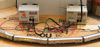
Wiring for Digital Command Control
DCCWiki, a community DCC encyclopedia.
The following pages explain DCC wiring concepts, methods, and best practices. Please note that there varying opinions on how to wire a layout. These articles do their best to provide generally accepted principles and wiring guidelines. You control your trains, not the track.
Edit a page if you find the information incorrect.
Wiring is extremely important for reliable DCC operation and signal integrity. Digital Command Control is not Analog DC, and the wiring practices for analog operations do not apply here. Your focus is on controlling the trains, not controlling the track voltage.
General Topics
- Wiring Tools – To manipulate wiring, you'll need various tools.
- Wiring Complexity – Wiring for your layout can be as simple or as complex as needed or desired.
- Wiring Color Code – It's important to develop a colour code when you're just getting started. It's even more important to stick to it!
- Wire Sizes and Spacing – How thick is too thick?How far apart should the track feeders be?
- Wire Types – Selecting the correct type of wire is important for the reliability of the DCC signal on the track.
- Voltage Drop – Model railroads have low tolerance for voltage drops throughout the layout. Be sure to use the proper wire gauge and feeder spacing.
- Twisting Power Bus Wires - Discussion on twisting power bus wires.
- Wiring Tips and Tricks - Various helpful hints and suggestions to make wiring easier and durable.
- Soldering - You'll need to solder some connections to form long physically and electrically durable connections
Additional Topics
- Converting to DCC - Also helpful if you're going to start with analog with a goal of using DCC later.
- Power Bus - All about wiring the power bus - the main wires that power your layout.
- LCC - Layout command control - A way to get information back from the layout.
- Program Track - How to safely wire a programming track
- Wiring for garden railroads
- Wiring large layouts
Track Wiring
- Wiring Your Layout The approach you'll take will depend on what type of project you are attempting. This page is intended to steer you in the right direction.
- Block detection – Block detection is a method for detecting rolling stock within a given section of track with the use of Accessory Decoders
- No Common Rail Wiring – In wiring for DC (analog) operations, modellers usually had one wire which was common to all blocks, the rail it connected to was not gapped over the entire layout. Do not do this for DCC!
- Reverse sections – Although the electrical phase on the rails does not control the direction of the loco, you still have to deal with reverse sections on your layout. If the track turns around back onto itself, the right rail will come in contact with the left rail, which will cause a short circuit; the same as placing a metal object across the rails.
- Turntables – Wiring Turntables
- Turnouts – Wiring Turnouts. For Digital Command Control things are a little different. What to look for, selecting turnouts, and other topics.
- Crossings – Wiring Crossings, Single and Double slips
- Crossovers and Slips – Wiring Single, Double and Scissor Crossovers.
