The Beginner’s Guide to Digital Command Control
Summary: DCC is an acronym for Digital Command Control, a standard created by the NMRA.
| Tutorial Topics |
|
| DCC Core Topics |
|
What is DCC?
Digital Command Control is a mechanism for controlling locomotives, and therefore trains, in a more realistic fashion than an old rheostat-based power pack.
- DCC allows multiple locomotives to operate independently on a layout. You control the locomotive, not the layout.
- DCC allows a locomotive's headlight, ditch lights, and optionally, other functions to be operated interactively.
- DCC allows multiple locomotives to operate cooperatively – as in an MU'ed pair of Geeps hauling a local freight, or the 2-8-4 pusher on that killer 4% grade.
- A locomotive equipped with a DCC sound decoder supports interactive, as well as automatic sounds.
- Operator activated sounds might include: the horn, whistle, bell, brakes, coupler, sanding valve, etc.
- Automatic sounds might include: steam chuff, prime mover, dynamic brakes, radiator fan, compressor, etc.
|
See the Video. |
Why Do I Need Digital Command Control?
If you're happy with your current layout and your current ability to control trains, then you don't need DCC.
But if you'd like to do any of the following:
- Operate multiple trains simultaneously
- Support multiple operators
- Offer pusher service to trains climbing that grade
- MU your three new Tier-4 locomotives
- Add sound to your locomotives
- Have wireless control of your layout
Then Digital Command Control may be just what you need.
Will Digital Command Control Work on My Layout?
- Main article: Adapting DCC to Your Layout
Digital Command Control will operate on any model railroad, from 'Z' scale to 'G' scale, or larger. DCC works on 2-rail or 3-rail, battery operated locos, indoors or out. DCC is highly recommended for new layouts, and can be retrofitted to any layout.


Overview of Digital Command Control System

Digital Command Control System Components
Digital Command Control systems can be as complex or as simple as you want. To get started, you only need the following items:
- Throttle
- The controller for the layout, also known as the cab, and is often handheld. This is used by the operator to control a locomotive, or a group of locomotives in a single train. Throttles send control commands to the Command Station
- Command Station
- This is the brains of the layout. Its job is to collect inputs from throttles, process them, then send those signals to the train via a booster. Sometimes called the Central Station.
- Booster
- The booster receives commands from the Command Station, amplifies and delivers them to the track. May also be called a Power Station.
- Decoder
- A multifunction decoder is a small electronic device installed inside a locomotive and is responsible for responding to commands from the command station. Unless you're using battery power, the rails are always powered at 100%. It's the decoder that decides how much power to deliver to the locomotive's motors, play sounds, or control lights.
In practice, command stations are often integrated with the booster into a single unit. Some starter sets combine the throttle, command station and booster. As the layout grows or needs more power, additional boosters may be added. Only one command station can be used as it will send commands to all the boosters. Regardless of how the system is packaged, the basic functions of the diagram are present in every DCC system.
Command Station
- Main article: Command station
The Command Station is the "Grand Central Terminal" of the DCC system – everything is routed through the command station. The command station accumulates all operator requests from every throttle in the system. It encodes each request into a standard DCC command packet, broadcasts each packet to every booster in the system via the booster bus or throttle network. Though your layout may have many throttles and a few boosters, the layout requires only one command station.
When evaluating potential DCC systems for your layout, consider not only the number of trains you need to run today, but how many you and your operators might be running in the future. If you see yourself running a lot of trains, chose a system with a command station that has the future capacity you need.
The features offered by a DCC system are dependent on the command station. Some command stations have a very limited feature set, while others have extensive features and options available. Be sure to compare the available features when selecting a starter set. Some systems may offer limited expansion possibilities, while others offer a wide range of potential for future expansion.
Command stations are substantial information processors. Modern command stations contain one or more microcontrollers, executing code embedded in firmware. Many command stations provide a mechanism to update themselves by simply loading new firmware.
Today, many command stations and their associated boosters are integrated into the same package.
Throttles and Throttle Jacks
- Main article: Throttle
The throttle (also known as the cab) is the controller, often handheld, used by the operator to control a single locomotive, or a group of locomotives in a single train. Additionally, modern throttles allow the operator to manipulate features beyond the scope of a locomotive, like turnouts, or any other layout feature connected to an accessory decoder. Throttles connect to the throttle network. Throttles are brand-specific, throttles from different manufacturers cannot be interchanged. The throttle bus is not part of the DCC Standard, giving manufacturers the freedom to design a throttle bus to suit their requirements.

Manufacturers design their DCC systems to support multiple throttles, in some cases with support for as many as 100.[1] Many throttles need to be plugged into something to communicate with the command station. The ports that throttles connect to is referred to as 'jacks' and allows throttles access to the throttle bus. Although a command station may limit the number of throttles connected at one time, there's usually no limit to the number of jacks that can be installed. This allows a layout to be designed such that operators can follow their train around the track, taking their throttle with them and plug into other places.
As an alternative to an array of throttle jacks decorating a layout's façade, with the addition of a wireless gateway any number of throttles, up to your system's maximum throttle capacity, may be wireless.
Modern throttles include a significant amount of processing power. Most contain one or more microcontrollers, executing code embedded in firmware. This firmware-based architecture allows many throttles to be updated by simply loading new firmware. In many cases adding a newer throttle can unlock additional functions and features.
At least one throttle is required in your system; most layouts have a several. For throughput reasons, DCC manufacturers must limit the number of throttles allowed, so there is a "Maximum Throttle Capacity" for each manufacturer's DCC system (see the Starter Set List for more details).
Be sure to read the throttle article to learn about different types of throttles.
Power Supply
- Main article: Power Supply

For simplicity, stand-alone power supplies are not shown on the functional block diagram above, however they are required by most DCC components.
Most throttles draw their required power from the throttle bus, supplied by the command station.

Components like the command station and wireless gateway are often powered by "wall wart" power supplies – those small, inexpensive power supplies designed to plug directly into wall outlets and suspend themselves from those outlets.
Boosters require a more substantial power source than a wall wart. Depending on your booster's requirements, its power supply requirement might be a 2 to 10 amp unregulated or regulated DC supply, or an AC supply of suitable current and voltage.
Booster
- Main article: Booster
The booster is a digital signal amplifier. Each booster accepts packets from the booster bus and amplifies them to the track voltage required. For a small layout with a few locomotives, one booster may be sufficient. For a large layout with dozens of locomotives, several boosters may be required. It's not the size of a layout the determines the number of boosters required, it's the number of locomotives [and other DCC loads] that determine the number of boosters.

The input to each booster is shared – the command station broadcasts packets on the booster bus – but the output of each booster is connected to a unique portion of track called a power district. Power districts are created by introducing rail gaps at district boundaries. Districts are a mechanism for electrical "load management" – they are introduced to limit the number of locomotives any single booster must drive.
Generally, boosters are dumb devices (little or no onboard intelligence) which simply amplify whatever signal is present on the booster bus. As a result, it is possible to add boosters from another manufacturer, subject to some limitations. It is best to verify compatibility before investing in a booster from another brand.
With DCC, full power is applied to the track, regardless if a train or other item on the layout is doing anything. In DCC, it is true that you operate the trains, not the track.
Booster Bus
- Main article: Booster#Booster Network
Often called the booster network, the booster bus is the interconnect between the command station and all boosters in your system.
Though some booster buses support bi-directional communication, where the command station can also receive information from a booster, conceptually the booster bus can be thought of as a unidirectional command-station-to-booster bus.
Again, your DCC system will restrict the network topology of the booster bus you are allowed to deploy on your layout. Your booster bus, for example, might have a maximum overall length, the booster bus might require a linear bus topology (no branches), or there may be special terminations required at the end of its branches. It may also limit the number of devices on the network, and require devices to have specific addresses.
Decoders
- Main article: Decoder
A decoder is the device which receives DCC commands and acts on them. A decoder is pre-programmed (by the installer) to a specific address. The decoder monitors all DCC commands, but it only acts on those commands addressed to it. Usually the term ‘’DCC Decoder’’ refers to a Multifunction Decoder. Generally, multifunction decoders are mounted in and used for controlling locomotives.
Accessory (stationary) Decoders are mounted under or around a layout, for controlling accessories such as layout lighting, sounds, or other animations.
DCC decoders can be customized using defined Configuration Variables (CVs), the most basic configuration being the pre-programmed address. A decoder only responds to commands sent to its address, or special commands such as the Emergency Stop.
- Multifunction and Accessory Decoders
A multifunction DCC decoder with an optional "keep alive" capacitor
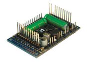
Multifunction Decoder for a large-scale locomotive
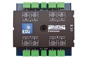
Accessory Decoder for controlling accessories such as turnouts
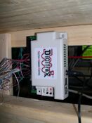
Accessory Decoder mounted under the benchwork


Multifunction Decoder
- Main article: Multifunction Decoder

Multifunction decoder means just that: It controls multiple functions: Motor, Lighting and more. It is installed in a locomotive or its tender, or in another car such as a boxcar if it cannot fit in the locomotive. The multifunction decoder monitors all DCC commands on the track, but only acts on those addressed to it, controlling the locomotive's speed, direction, lights, sound effects, etc. Many multifunction decoders now offer sound and sophisticated lighting functions.
Accessory Decoder
- Main article: Accessory Decoder
Accessory Decoders control fixed items, such as turnouts, crossing gates, signals, etc. A very typical application is the remote control of turnouts. Accessory decoders can be powered from the track or from their own power supply. Commands can be received via the track or via an alternative accessory decoder bus. Many accessory decoders can also connect to a compatible throttle network. Accessory decoders can be simple on-off controllers, or allow a degree of automation themselves, or be controlled by a computer running the appropriate software.
The DCC standard defines a specific addressing scheme for accessory decoders so they only react to commands sent to them, ignoring commands meant for multifunction decoders.
Function Only Decoders
- Main article: Function Decoder
These are simple decoders, often installed in rolling stock. Used to control lighting effects, such as marker lamps and interior lights on a caboose, or interior lighting on a passenger car. They can be controlled by the throttle, allowing you to turn the interior lights on or off, and in the case of marker lights, switch them on to match the direction of travel. They were also used with a multifunction decoder to provide additional functions such as classification and ditch lights, controlling number board illumination and other lighting effects.
There is a sub-class of these decoders which provide sound only. They provide the sound of mechanical refrigeration units in reefer cars, or of animals in a stock car. While today a sound decoder is often integrated into a multifunction decoder, they did exist as a separate device used in conjunction with a locomotive's multifunction decoder.
Programming Track
- Main article: Programming track
Many DCC systems support a dedicated programming track output. These outputs are designed to allow easier programming of installed decoders, limiting the power available to prevent damage if a mistake was made during installation. The programming track can be part of the layout, or a special track on your workbench. For some sound decoders you may need a programming track booster.
Computer Interface
- Main article: computer interface
Many DCC systems offer a specific device [not shown in the block diagram above] providing a computer interface into the DCC system. This gateway or portal device usually connects thru the throttle bus providing a USB or serial interface to a laptop, desktop, or tablet computer. By running suitable software on the computer, various degrees of DCC configuration and automation are supported.
Final Review
- Main article: How Does Digital Command Control Work
In summary, the command station collects inputs from throttles or computer interfaces from the throttle bus, prioritizes those commands. It then sends those commands to the boosters, using the booster bus, where various decoders will receive the commands and perform actions as requested.
Where to Go from Here
- Continue on to the Introduction to DCC part 2 of this introduction.
- Digital Command Control Advantages Over Direct Current may help deciding between DC powered or DCC powered layouts.
- Read Selecting A Digital Command Control System, and the companion article, Checklist for Choosing a Digital Command Control System.
- Don't miss the DCC Systems comparison.
- As you prepare to select your first DCC components, check out the Starter Set article.
- Check out the library of Tutorials and the list of Frequently Asked Questions.
- Confused? Read the DCC Myths to answer those opinions you have heard about DCC
- Consult the list of DCC Resources.
- And when you're ready for it, study the article Wiring for Digital Command Control, and it sub-articles.
Videos
Be sure to look at the Video Page: Videos:Contents.
DCC Model Trains and Model Railroads Explained
Video: Bruce Petrarca MMR - ABCs of DCC
Another of the NMRAx Virtual Convention Clinics presented in May 2020.
The Basics of DCC
- ↑ The exception is a very basic system supporting a limited number of additional throttles.