VH Royal Hudson
Summary: Converting a Brass Locomotive to DCC operation. This example was originally equipped with Hornby's Zero1 system which is not compatible with DCC.
| See more Decoder Installs | |
|---|---|
| |
| General information | |
| Original Author | User:Terminator |
| Scale | HO |
| Est. Install Time | |
| Date Installed | 2008 |
| Decoder Product | DH123D |
| Installed Into Product | Van Hobbies Brass Royal Hudson |
| Keywords Brass locomotive, Tenshodo, royal hudson | |
Van Hobbies/Tenshodo Royal Hudson Decoder Install
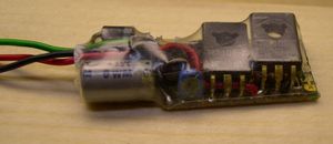
Upgrading a Tenshodo Brass Royal Hudson to DCC. A Digitrax DH123D decoder will be installed. Rated at 1.5A, 2A peak.
This example was equipped with Hornby's Zero1 technology, one of the first command control systems on the market based on digital, not analog technology. The Zero 1 system is not compatible with DCC.
Many Brass Locomotives will be similar to this one for conversion. Basic, no sound.
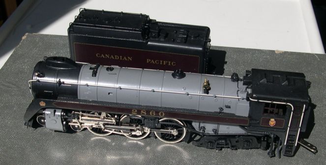
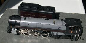
A brass locomotive, with custom paint job, an investment worth over a thousand dollars. Not the only improvement you can make with a soldering iron, but conversion to DCC will make it even better.
So, if you have the guts and the tools, it can be done.
Tenshodo Royal Hudson in Brass
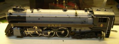
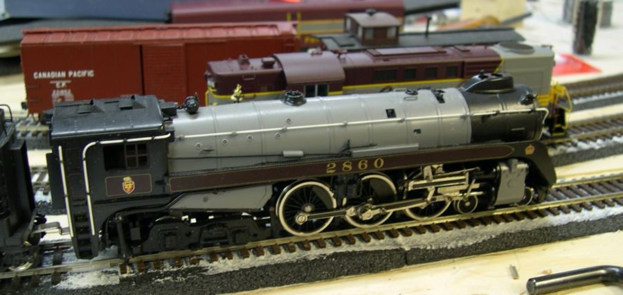
This is the conversion of a brass locomotive to DCC operation. The model is a Tenshodo CPR Class H1e, Road No. 2860, 4-6-4 Royal Hudson.The unit was originally converted from DC operation to Hornby's Zero 1 system. It was originally imported by Van Hobbies in Vancouver, British Columbia.
This article deals with converting the locomotive to DCC operation. A basic Digitrax decoder will be installed in the boiler, replacing the Zero 1 decoder already installed.
This model dates to the mid 1970s.
Important Note Regarding the Zero1 Receiver
The Zero 1 system used three wires, not four like DCC. As such, the frame is electrically connected to the motor. (It is not isolated from the frame.) Be sure to isolate the motor from the frame or the multifunction decoder replacing it will be damaged.
The Royal Hudson
The Royal Hudson is a unique version of the 4-6-4 Hudson, owned and operated by Canadian Pacific.
In 1939 Canadian Pacific assigned Class H1d Hudsons 2850 and 2851 to the Royal Train for the visit of King George VI and Queen Elizabeth. This was the first Royal Visit to another country in the Empire.
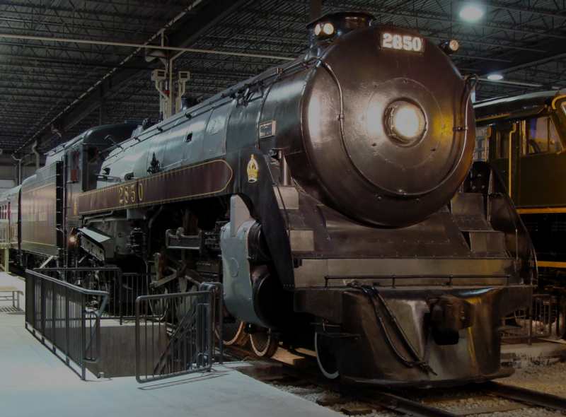
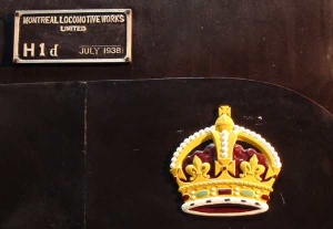
H1d Hudson 2850 was painted in Royal Blue and silver, with stainless steel boiler jacket, cylinder casings and grabirons, the royal crests in relief on the tender sides and smokebox front. Gold royal crowns were fitted to the running board sheathing on both sides above the cylinders. Number 2851 retained her regular paint, with the exception of the gold crowns above the cylinders. They were selected for their proven reliability. 2850 had already proven herself in her first revenue trip, a 32 hour Thunder Bay to Calgary passenger run.
2851 would pull the pilot train with the press and politicians, and exactly one hour later 2850 would arrive with the King's train. The King was a bit of a railfan himself, and rode in the cab of 2850 whenever he could. After flawless performance hauling a large train for 3224 miles, the trip from Quebec City to Vancouver was completed. (The return trip, run by Canadian National, required (it is said) from three to nine locomotive changes.)
Both 2859 and 2851 established records for length of series, with both locomotives remaining at the head of their trains for the greater part of their 6000 mile (9656 km) tour.
After the Royal Tour was completed, H1d 2850 in its royal tour livery went to the World's Fair in New York, USA, as part of the Railroads on Parade pageant, where it participated daily in the pageant finale. A B&O engineer, Walter Evans, was at the throttle for the parade, and was very impressed by the smooth handling of the locomotive.
Upon completion of the trip, King George gave Canadian Pacific permission to rename the 2850 through 2864 semi-streamlined class as Royal Hudsons and to apply the gold crowns to the running boards. They are the only locomotives outside of Britain to carry a "Royal" designation. After service on the Royal Train 2850 travelled to the New York World's Fair the stainless steel boiler jacket was removed and stored until 1951 when it was installed on another Royal Hudson assigned to Princess (now Queen) Elizabeth's train during her visit to Canada.
Royal Hudson #2850 [1] is now on static display at Exporail in her normal livery, and two coaches from the Royal Train are in storage at the Museum of Science and Technology in Ottawa. Royal Hudson 2850 has been designated a National Historic Site.
Class H1e, Royal Hudson 2860 is currently in British Columbia and is used for excursion service. It did a cross country tour in the late 1970's promoting tourism for the province of British Columbia. 2860 (and CPR's Empress 2816, a H1b Hudson) may make an appearance in Vancouver for the 2010 Olympics. The build plate for 2850 says H1d. The 2860 was the first locomotive constructed as a Royal Hudson, hence the H1e designation. All the previous units were in service when they received the "Royal" designation and the crowns were installed.
Royal Hudson 2860 was the first of the last of 5 Royal Hudsons (2860-2864) erected at the Montreal Locomotive Works (ALCO) in June 1940.
All Royal Hudsons were retired from service by 1960 and many were scrapped. 2860 derailed in 1956, but was refurbished and placed in service until 1959, when she went to the dead line. The shop crews didn't want to cut her up, so she sat for 5 years. In 1964 she was purchased by a museum, but again sat in storage until 1970, when sold to a private owner. In 1973 she was sold to the government of BC, rebuillt at the CPR shops in Vancouver, and went to work hauling excursions afterwards. Canadian Pacific presented 2850 to Exporail.
Important
- Read all the manufacturer's literature first.
Wear safety glasses during soldering. Solder can splash. Remember, soldering involves high temperatures.
Proper tools are important. Screwdrivers should be sharp as damaged screwdrivers can slip and hurt you, or damage the finish of the locomotive. Always use the correctly sized screwdriver to minimize accidents.
For this installation in particular, an Ohmmeter is a must. A Digital Multimeter (DMM) or a V-O-M (Volt Ohm Meter) is needed to check continuity, and insure the motor is isolated from the frame. Get a good one, as they have many applications on the layout for troubleshooting electrical problems, and other household applications. For brass steam in particular, a multimeter is very useful, as the frame is usually hot, and the tender completes the circuit.
If you are storing a brass locomotive, wrap it in plastic film to protect it from the foam packaging, which can degrade over time and damage the finish. Always keep the boxes they came in for that purpose. Protect your investment.
Selecting a Locomotive
Brass locomotives are gorgeous examples of handcrafted work. They are usually rare models not found in plastic. But, how they run is not determined by their appearance. Brass locomotives may need some TLC and adjustment just to run nicely, and may even need repowering and new gear trains. Select a locomotive that runs well on DC (analog) power first, and be sure to do the stall test. That can be done by grabbing the drivers to stall the motor.
The investment in time getting the engine running well before conversion will pay off. You may have to ask the dealer for help on this. Otherwise the geartrain could bind at some point, and probably destroy the decoder. This is very important for steam locomotives. A properly tuned and adjusted mechanism should only require slight finger pressure to push it down the track. (The gearbox is disassembled at this point.) If you want mechanisms that are easy to adjust and almost trouble free, stick to diesels.
Remember, many brass locomotives use the frame to complete the electrical circuit. If the motor is electrically bonded to the frame, a damaged DCC decoder will result. Check the connections at the motor and correct as needed.
Preparations
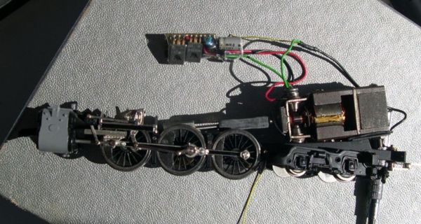
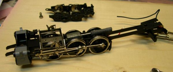
Chassis after disassembly. Note the Zero One decoder.
In order to install the decoder, some disassembly is needed. Brass steam locomotives typically complete the electrical circuit through the tender. The frame is hot!
This model had three screws holding the cab and boiler assembly onto the frame. Two were under the cab and a third in the front. The front screw consisted of a stud, with a nut, which held the front truck on. After removing the lead truck, remove the nut holding the cylinder assembly in place, and carefully remove the body.
In order to tear out the Zero 1 decoder hidden in the middle of the boiler, four screws were removed and the lower boiler half carefully removed. This piece includes the weights. At this point, put the boiler aside, as the running gear is of interest. It may be prudent to remove the trailing truck at this time. Put all the pieces someplace safe, and all the screws, etc., into a container so you won't lose them.
Preliminary inspection
Chassis with motor removed. Note the wire at the rear of the frame and the insulated washer. This is the connection to the tender to complete the circuit.
Assuming you have tested the current draw of the drivetrain, and the locomotive runs well, the next step is electrical tests.
Using an ohmmeter, check which rail the frame is connected to, it may be the engineer's side. Also check that the motor is isolated from the frame.
Motor
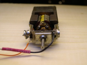
This example uses an open frame motor, and the motor chassis is hot. So it will need to be isolated. The motor sits on a plastic shim, held in by two screws. The screws connect the motor electrically as well. To save time and effort, the manufacturer soldered the negative brush (black wire) connection to the frame. (See the picture.)
Since this locomotive was originally equipped with a Zero 1 decoder, a black wire connected from the negative brush/frame to the decoder. Zero 1 decoders only had three wires, as they were designed easy installation in Hornby locomotives, most of which bonded the motor to the frame to simplify wiring at the factory.
Carefully removing the solder and bending the tab away will isolate the motor from the frame. You need a hot soldering iron for this procedure.
Mounting Hardware
Another possibility would be to replace the metal machine screws with nylon equivalents. The rearmost screw goes from the top of the motor, through a threaded hole at the bottom, with a nut installed to secure the motor. There is a slot in the frame allowing the motor screw and nut to slide in. A second screw is used to secure the motor in place and maintain alignment. Walthers does list plastic screws, but they may not have the sizes needed. An electronics supplier may be helpful here.
Harness
For this application a Digitrax DH123D was recommended by the dealer. It comes with a harness, which plugs into the decoder PCB. It only has two function outputs, but being a steam locomotive used in passenger service, it really doesn't need to back up. Adding a reverse light would require two additional wires running to the tender to control a lamp or LED.
Installing a decoder with extra functions is a possibility, making cab lights and firebox flicker possible. This locomotive was oil fired, so an orange/red LED would provide additional realism in the firebox.
Wiring
The harness is connected as follows:
Red wire is the pickup on the engineer's side, and black is the fireman's pickup. In this case, the black wire will be connected to the tender drawbar to complete the circuit. The red wire will be connected to the the boiler or frame at some point.
The orange wire goes to the motor's positive brush (the one on top here,) and the grey to the negative brush. As always, reverse the leads if the engine runs backwards. A small connector (non-polarized) would be helpful, and allow you to separate the boiler from the motor leads.
The white wire is the headlight feed and the yellow one is the reverse lamp. Blue is the common line for the lighting. You can tie both together if you want the lamp on in either direction.
The Violet and Green leads are not used.
Headlight
For simplicity, a bulb will be used for forward lighting. It is installed by pushing the wires into the headlight assembly from the front, then reaching into the boiler and pulling them and the bulb into the housing. As this is a metal chassis, the leads must be insulated, or you may get a short from the decoder to the chassis. The bulb will be 12VDC in this install. The original bulb was burnt out, (probably destroyed by the 22V used by the Zero 1 system) and simply connected in parallel with the motor. A resistor will reduce the current and extend the life of the bulb.
Some drilling would be needed to enlarge the hole at the back of the housing for a LED.
Incandescent Lamp Current Draw
Read your decoder specifications, and note the maximum current draw permitted for lighting circuits. Keep in mind that as a rule, a lamp when cold will be capable of passing current at a level four times or more of that of the current draw while on (hot.) The inrush current should not exceed that of the decoder's specifications.
Decoder Install
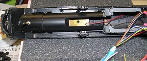
Red wire connects to boiler for power.
The decoder will be mounted in the boiler. It will be connected to the harness and pushed into postion. Ensure the leads are not pinched, especially the lamp wiring which will travel between the boiler jacket and weight. It can be held in place with double sided adhesive tape.
Power is delivered to the decoder by the red wire, soldered to a brass plate in the roof of the boiler. This operation was done before the boiler weight was installed. Be careful not to damage the paint with the hot iron. You need a large tip and a hot iron for this operation. Place the boiler on a soft surface to prevent damage to details and paint.
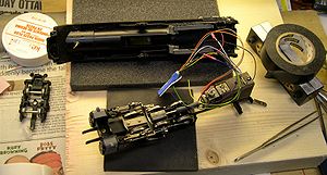
The decoder will fit in there too, using double sided tape to secure it in place. The boiler weight has been installed, and the headlamp wires are running under the plate as well. Most of the wiring can be tucked up into that area.
Reassembly
Before proceeding, make sure the motor is isolated from the frame, and that no wires touch the frame (other than the one that provides power.)
Reassembly is straight forward. Carefully place the boiler on the chassis, after tucking the wires into the boiler. The motor will occupy most of the Cab and firebox area. As the motor is narrow, wires can run up beside it without much problem. Carefully route the black wire which attaches to the drawbar.
Once the boiler is on, and the wires neatly placed, install the hardware the holds everything together, and re-install the front truck and trailing truck.
Programming
The next stage is programming the decoder. Reset the decoder, then set the address, and the locomotive is ready for service. The decoder for this install is pretty simple. Other possibilities include reverse lighting on the tender, and firebox flicker, depending on the feature set of the decoder chosen.
- The locomotive will not work without the tender. It needs it to complete the circuit. If the decoder doesn't respond, check that the tender has a good connection with the locomotive. Some brass locomotives may have a wire with a pin that mates with a connector on one of the units for a better connection. If a short occurs, verify the wheels on the tender are correctly installed. One wheelset reversed will cause a short.
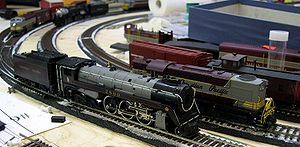
Be careful not to allow the tender and cab to touch in a curve, as this will result in a short. Adjust the tender distance as needed to prevent this. As shown in the image, the tender should be coupled a lot closer, as per the prototype.The prototype is close coupled, maybe 3 feet between tender and cab. But electrically, that would be a problem, and the locomotive would probably be derailing on curves.
With that, the conversion is finished. The locomotive is ready for revenue service, hauling passengers, freight, or maybe an excursion train, as the prototype has done.
Notes
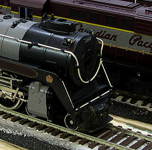
Two images of the completed project. The closeup of the locomotive shows why long term storage of brass in the original packaging is a bad idea. The foam rotted and became affixed to the model, and the paint was damaged in the process. The pilot had to be repainted after the foam residue was removed, as the process also removed the paint. Wrapping the model in plastic wrap is probably not a bad idea. Protect your investment.
The open frame motor is rather noisy, and takes a lot of power to get moving. Some adjustments of the VStart, etc., are warranted. Once rolling, the locomotive steams along at a nice clip. This model is a definite candidate for remotoring. This locomotive may date from the 1970s, so remotoring would probably be a great improvement.
Conversion from Open Frame to Can Motor
- Install a new motor. This model was upgraded to a new flat can motor for better performance. A low cost way to improve any locomotive with an old or noisy motor. Older models may run slower and have higher current demand as the magnets in the motor weaken over time. Replacing the motor with a new one cures those issues.
Coreless Motor Warning
Some brass models may come with a coreless motor. Do not run the model on DCC without a decoder, as the motor will be damaged. If the model does have a coreless motor, select a decider compatible with it. Low frequency PWM may also damage the motor, so a high frequency decoder is required.
Rocky Mountain Express in IMAX
Related FAQs
- No FAQs link to this page.
See Also
- Decoder - More about decoders
- Digitrax - Digitrax information
- No. 2858, preserved at the Canada Museum of Science and Technology.
- A Royal Calling
- The story of the Royal Hudson #2860
- Royal Canadian Mint #2860 Silver $20 coin
