Locomotive Interface/NMRA Eight Pin Plug
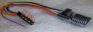
Summary: DCC-ready locomotives with 8-pin sockets are shipped with a factory-installed 8 pin blanking plug that shorts the rail pickups to the motor terminals (and headlights) in the absence of a decoder. This plug must be removed before installing the decoder and must be replaced if removing the decoder and returning it to analog operation. The 8 pin version is known as the medium size and was the most common standard DCC connector used in HO and OO locomotives.
For this article the term NMRA 8 Pin will be used.
Obsolescence
The 8-pin connection is considered obsolete and no longer supported by the NMRA. It lacks connections for additional functions and speakers, which are present on recent locomotive decoder interfaces. The NMRA recommends that this connection no longer be used by manufacturers.
Connections
| PIN ASSIGNMENTS | |||
|---|---|---|---|
| Pin # | Small, Six Pin | Medium, Eight Pin | Large, Four Pin |
| 1 | Orange | Orange | Grey |
| 2 | Grey | Yellow | Orange |
| 3 | Red | Option | Black |
| 4 | Black | Black | Red |
| 5 | White | Grey | N/A |
| 6 | Yellow | White | N/A |
| 7 | N/A | Blue | N/A |
| 8 | N/A | Red | N/A |
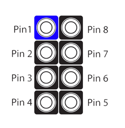
This table depicts the pin assignment of the NMRA Medium 8-pin plug or 8-pin socket (both viewed from above). Although the wiring is designed to work properly one way round, no harm is done if it is inserted the other way round by mistake (but the lights will not work). This plug and socket combination is identical to the NEM 8-pin plug and socket (defined by NEM 652) used in Europe.
Pin 1 should be clearly marked on the plug and socket with a small triangle or dot.
In the case of a 'three function' or 'four function' decoder with an 8-pin plug there may be a green F1 (Function 1) wire connected to Pin 3, although this is not required by the standard specification. Decoders and locomotives with or without pin 3 in use should be interchangeable, i.e. a decoder without an F1 output can be used in a locomotive with an F1 input (but the function won't work) and a decoder with an F1 output can be used in a locomotive with an F1 input (but the function won't do anything).
When soldering wires onto the connector, use the cup side.
Testing the NMRA 8 Pin Connector
It is possible that, while the manufacturer has installed an 8-pin interface, it is wired incorrectly. Failing to isolate the motor terminals from the rail connections will destroy your decoder.
Testing the Interface
You will need a DMM for this process, on the Ohms (Ω) setting. Touch the probes together to verify the meter is working, the display should show a very low resistance (0 or slightly more). If using an analog ohmmeter use the zero-adjustment knob to bring the needle to "zero".
Motor Connections
- Remove the dummy plug and set it aside.
Measure the resistance between the following points:
- Pins 1 and 8, then
- 1 and 4
- 5 and 8
- 5 and 4
The DMM display should indicate an open circuit (infinite (∞) resistance) on all the above combinations. If using an analog ohmmeter, the needle should not move.
Headlight Connections
- Remove the dummy plug and set it aside.
- Touch the DMM probes to pins 2 and 8 then
- 6 and 8
- 7 and 8
- 4 and 2
- 4 and 6
- 4 and 7
The DMM display should indicate an open circuit (infinite (∞) resistance) on all the above combinations. If using an analog ohmmeter, the needle should not move.
Specifications
The 8-pin connector has the following specifications:
- 2 x 4 eight pins at 0.1" pitch
- 1.5A contact rating (maximum sustained load)
- 3.0A peak contact rating
The contact ratings are for the individual pins of the connector only and do not reflect the capabilities of a particular decoder or requirements of a particular locomotive. For example, if a locomotive's maximum sustained motor current is over 1.5A, this plug and socket should not be used.
This information is based on NMRA S-9.1.1 Electrical Interface & Wire Color Code, which also describes the small and large sized alternative plugs, with further information provided by the Digitrax DZ143PS instruction manual and the Soundtraxx Tech Note 16.
[https://www.morop.org/downloads/nem/fr/nem652_f.pdf NEM 652 standard, in French.
See Also
- NMRA_DCC_Plug - Comparison of NMRA DCC Plugs

