Locomotive Interface
Summary: The NMRA and NEM adopted standard mechanical and electrical interfaces to connect Multifunction Decoders to a locomotive's electrical system. These plugs and sockets make it simpler to install a decoder into a suitably equipped locomotive. In many cases a blanking plug must be removed before installing the decoder. If a locomotive is not DCC-Ready it will lack an interface and must use a Hardwired Decoder or a drop-in replacement DCC control board (if available) for that specific model.
|
See the Video. |
NMRA and NEM Connectors
| Name | NMRA | NEM |
|---|---|---|
| 4 Pin | NMRA Large | NEM 654 |
| 6 Pin | NMRA Small | NEM 651 |
| 8 Pin | NMRA Medium | NEM 652 |
| 21MTC | 21MTC | NEM 660 |
| Next18/Next18–S | Next18/Next18–S | NEM 662 |
| PluX | PluX8/16/22 | NEM 658 |
NMRA and NEM 6, 8 and 4 Pin Interfaces
- Main article: Locomotive Interface/NMRA Eight Pin Plug
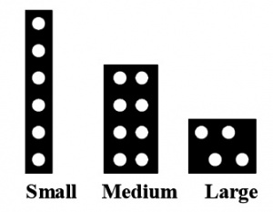
The NMRA is discouraging the use of the 4, 6 and 8 pin interfaces in new models.
These interfaces are designed for basic installations without sound or many additional functions. The various sizes are intended to cope with the various physical size and power requirements for different scales.
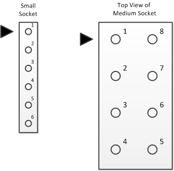
The 6 pin small interface is intended for N gauge locomotives due to their restrictive size and lower power requirements. The locomotive side is a 1x6 female socket with 0.05" pitch. It is also called a NEM 651 plug.
The 8 pin medium interface is intended for HO/OO gauge locomotives and allows for slightly higher power and simplifies headlight wiring. The locomotive side is a 2x4 female socket with 0.1" pitch. Also known as the NEM 652 plug.
The 4-pin large interface (NEM 654) is intended for O gauge and above and allows for higher power. The locomotive side is 4 male pins, the decoder side is 4 female sockets. The standards do not define the physical connector layout.
Pin Assignments and Wire Colours
- Main article: Locomotive Interface/NMRA Connector Wiring
| PIN ASSIGNMENTS BY COLOUR | |||
|---|---|---|---|
| DCCWiki.com | |||
| These Connector Types are now Obsolete. | |||
| Pin # | Small, Six Pin | Medium, Eight Pin | Large, Four Pin |
| 1 | Orange | Orange | Grey |
| 2 | Grey | Yellow | Orange |
| 3 | Red | Output 3 / Aux 1[1] | Black |
| 4 | Black | Black | Red |
| 5 | White | Grey | N/A |
| 6 | Yellow | White | |
| 7 | N/A | Blue | |
| 8 | Red | ||
21MTC Interface
- Main article: 21MTC
The 21MTC Connector interface is a standard adopted by both the NMRA and NEM 660. Its name comes from 21 pin Marklin/Trix Connector, developed by Marklin and ESU. It is often found in locomotives with OEM decoders from ESU. There are differences between the NMRA and NEM definitions for this interface.
In December 2020 the NMRA updated their interface standards and has adopted the NEM definitions as the official NMRA standard for the 21MTC connector. In time all 21MTC multifunction decoder manufactures will incorporate the combined NEM/NMRA 21MTC interface. Older models and multifunction decoders may still be available which follow the older (now superseded) NMRA pin assignments. Verify the pinouts before installing a decoder.
This interface is always a direct-connect type as there is no wiring harness. The decoder plugs directly on to the male header mounted on the locomotive chassis.
The NMRA standard has discouraged the use of this connector in new locomotive designs from January 2010. It is intended to be replaced by the PluX interface.
The main physical difference between the 21MTC and PluX decoders is the pin arrangement. The 21MTC features a female socket which mates with pins on the locomotive interface. The PluX is the opposite: the pins are on the decoder, which mate with a female connector on the locomotive. The PluX standard defines the length of the pins, as they pass through the locomotive interface board for a lower profile installation. Verify the alignment with the documentation that came with the decoder, as the connection may not be keyed to prevent incorrect alignment.
If a manufacturer states the locomotive comes with a 21-pin decoder, it would indicate a 21MTC interface.
Next18 Interface
- Main article: Locomotive Interface/Next18
- NEM 662 / RCN-118
- NMRA S–9.1.1.5
MOROP created the Next18 standard for extremely tight applications, such as TT and N scale locomotives. The NMRA has not embraced the Next18 interface, though some manufacturers have. In addition to specifying the electrical interface and connectors, the NEM 662 standard also mandates the maximum physical size of decoders. A fully compliant Next18 decoder is no larger than 15mm x 9.5mm - one would fit on a dime; a Next18S decoder is no larger than 25mm x 10.5mm.
| Connection | Length | Width | Height |
|---|---|---|---|
| Next18 | 15 mm | 9.5 mm | 2.9 mm |
| Next18-S | 25mm | 10.5 mm | 4.1 mm |
There are two variants: Next18 and Next18–S. Next18 supports motor control, front and rear headlights and 6 auxiliary output functions; two of those function pins may be used to provide an on-board TrainBus serial interface. A Next18–S decoder sacrifices two auxiliary function outputs for the speaker connections.
PluX Interfaces
- Main article: PluX Interface
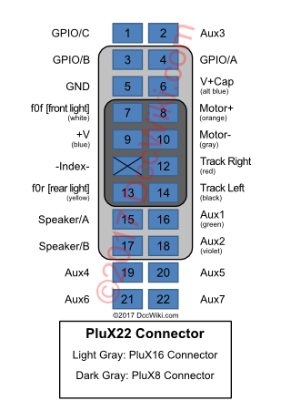
The NMRA and MOROP have adopted a newer standard interface called PluX22, and its subsets, PluX16 and PluX8. (MOROP's NEM 658 also defines PluX12, however, NMRA Standard S-9.1.1 does not.)
Purpose
The purpose is to provide a uniform interface for safe, secure and rapid installation of decoders adhering to the PluX Standard.
Description
The PluX22 connector consists of two rows of 11 pins. PluX16 and PluX8 connectors consist of two rows of 8 pins and 4 pins respectively. The smaller connectors are subsets of the larger interface. Mechanically, the interface defines male pins on the decoder which are meant to interface directly with a female connector on a locomotive's receiving board. The preferred board-to-board orientation being that the decoder pins pass through holes in the receiving board's PCB and enter the bottom of the female connector. This would keep the height to a minimum.
- PluX8 offers no advantages over the NEM 651 interface, so it not used.
- The interface is designed for direct plug-in installation. Connection via a cable is not provided for, and are outside the PluX Standard.
- The Standard sets maximum dimensions for the decoder -- both footprint and thickness. This allows for small, drop-in decoders.
- The PluX interface supports one motor, up to 9 function outputs and one sensor input.
- Also defined are the installation space and size of the decoder. Packaging must be labelled indicating a PluX16 or PluX22 device.
E24
- Main article: Locomotive Interface/E24
This is new interface from ESU. Not much detail is known about it at this time. It uses a J3200 connector that was used on the iPhone 6's camera. This is not a proprietary connector, it just hasn't been through the standardization process yet.
It is mainly used in their multifunction decoders designed for N Scale applications. If allows a lower profile and more connections than the Next18 interface. The ESU 53900 decoder tester includes this interface.
It is found on the LokSound 5 Nano, and the forthcoming LokPilot Nano.
Choosing the best Decoder Format for your Model
Additional Reading
- See the NMRA Standard S-9.1.1 for more information on connectors used to create various locomotive interfaces.
- Sources for Connectors for DCC Decoders
- MOROP NEM 651 Standard (in German) defining the European 6-pin DCC interface.
- MOROP NEM 652 Standard (in German) defining the European 8-pin DCC interface.
- MOROP NEM 654 Standard (in German) defining the European 4-pin DCC interface.
- MOROP NEM 658 Standard (in German) defining Plux22, Plux16, PluX12, and PluX8. (Google translation to English)
- MOROP NEM 660 Standard (in German) defining the 21MTC Interface. (Google translation to English)
- MOROP NEM 662 Standard (in German) defining the Next18 Interface. (Google translation to English)
Adapters
For more adapters, see the Other DCC Equipment List.
Decoder Buddy
A 21MTC adapter board is available from NixTrains called the Decoder Buddy.
This interface board works with decoders by Digitrax, ESU, SoundTraxx, and TCS, as well as other 21MTC decoders.
The Decoder Buddy replaces the standard DCC 8-pin loco motherboard.
Features:
- 10-pin socket and plug with wire-outs for all 21-pin decoder functions
- 10-pin plug fully removable for easy separation of loco shell and chassis
ESU
ESU offers a number of interface adapters which allow modern multifunction decoders to be used in older locomotives:
- 21MTC Interface Part # 51967 has a socket for plugging in a multifunction decoder, with solder points for connecting to the original wiring of the locomotive.
- 51968 or 51957, adapter board with transistor amplified outputs AUX3 to AUX10.
- 51958, adapter board for PluX22
- 51999, Adapter board Next18 for 6 amplified outputs. With soldering pads and wires
References
- ↑ This connection on the socket (in the locomotive) may be left unconnected, or may be connected to an an accessory. If connected to an accessory, the accessory must be protected by a diode, if it is polarity sensitive, to avoid any damage in case the plug is inserted the wrong way into the socket. On the plug, this connection may be left unconnected or may be connected to connection 7 or may be connected to a decoder’s function output. In all cases, the use of this connection must be documented by the manufacturer.


