Digital Multimeter/Digital Multimeter Notes
Summary: Attempting to measure the DCC voltage on your track with a Digital MultiMeter will introduce new problems and additional confusion. First problem: They are designed for 50/60Hz AC. Outside of that frequency, the results get interesting, as the sample rate is not fast enough for signals such as the DCC waveform, which introduces a huge amount of error and uncertainty.
Digital Multimeters
- Main article: Digital Multimeter
Most digital multimeters measure AC as an Average Value, unless marked as a "True RMS" meter. This assumes a pure Sinusoidal waveform. RMS performance is sometimes claimed for meters which report accurate RMS readings only at certain frequencies (usually low) and certain waveforms (essentially sine waves). Some manufacturers, such as Fluke, have a True RMS feature, which is really accurate compared to other brands, especially when compared to really cheap DMMs. Better DMMs (such as those by Fluke and other quality instrument makers) use additional calculations to arrive at the RMS value. Cheaper DMMs will use simple lower cost circuits to determine the voltage. The factory will simply adjust the meter to read the RMS value. Then there are the accuracy of the calibration standards used at the factory as a reference to calibrate the DMM.
Do not rely on the meter as being 100% accurate. For comparative measurements, it is acceptable.
Nyquist Theorem
For an analog signal to be accurately digitized, it must be sampled at a rate at least twice that of the highest frequency present. In other words, the highest frequency should only be no more than half the sampling frequency for accurate sampling and digitization. This underpins many everyday things, like digital audio on Compact Discs.
The maximum signal frequency is called the Nyquist Frequency, and the rule is the Nyquist Theorem.
Aliasing
When a signal is sampled too slowly (there are frequency components above the Nyquist frequency) the resulting digitized waveform is distorted. This distortion is called aliasing. It results from the mixing (or beating) between the signal frequency (in this case, the DCC signal frequency) and the sampling frequency. Low frequency harmonics are recorded instead of the actual signal.
- In general, the sampling frequency should be more than twice the highest frequency to be measured. A value of 5 times would be a good choice. Many analog to digital conversion circuits also contain an anti-aliasing filter to eliminate any signal frequencies above the Nyquist frequency.
What does Aliasing Mean?
A cheap DMM may only sample at 120 or 180 Hertz, as it is designed for a 60 Hz Sine Wave. A better one may use 300 or 360Hz for more accurate measurements. It may also have a filter to cut off any signals above 70Hz. DCC signals are 8 to 10 KiloHertz in frequency. Sampling will result in a lot of aliasing, making your readings inaccurate and misleading. The DCC signal is a square wave, so getting an accurate measurement becomes a problem.
High quality instruments may be able to sample frequencies up to 2kHz accurately, but at a cost.
Measurements
If you were to use an oscilloscope to measure the line voltage in your house (nominally 120 V AC (RMS)) you would see that the sine wave measures about 340V peak to peak. One half cycle peaks at approximately 170V. The RMS value, which is displayed by measuring instruments, is 70.7% of the peak value or 120VAC. You should see a nice, pure sine wave, unless you have a lot of distortion, caused by harmonics. A common source of harmonic distortion is a switching power supply.
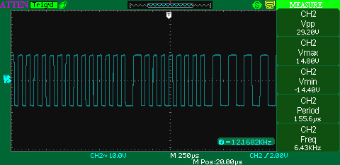
The same scope would display your DCC waveform as a square wave. It would accurately display the peak to peak value of the waveform. A square wave is actually the sum of sine waves at multiple frequencies, called harmonics. As more frequencies enter the equation, the waveform becomes more square in shape. The frequencies are harmonics of the fundamental frequency. You can calculate a sine wave and plot the result on graph paper, and as harmonics are added, the waveform becomes more and more distorted, until it forms a square wave. (This is how your kids burn out the tweeters in your stereo's speakers.) This is also important in your power bus, as excessive impedance causes distortion, as some frequencies will travel faster than others on the wire.
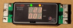
One solution is to use a rectifier circuit between the track and the DMM and measure the DC output of the rectifier. For more accurate results, you should characterize how the combination of DMM and rectifier works with high frequency complex waveform. Another solution is the RRampmeter mentioned above.
Why Measuring DC Volts Fails
Mathematically the DCC signal would be written as: (0+j14) + (0-j14), where the 0 is time on the X axis, the j operator indicates a voltage on the Y axis. These values show 14V at 90° and 14V at 270° on the oscilloscope display. Measuring this with a DMM set for direct current voltage results in the equation which sums the two values: (0+j14) + (0-j14) reducing to j14 - j14 = 0 DC Volts. Time is not important to this calculation as a meter measures amplitude only.
Since the signal switches states at a high frequency, a typical Digital MultiMeter (DMM) on ACVolts cannot sample the signal accurately. They do not sample at a high enough frequency to calculate the value accurately, as they are typically designed to measure AC in the 50-60 Hertz range. The instantaneous voltages it samples result in an erroneous value due to aliasing. Digital multimeters are designed to calculate and display the RMS value of a pure sine wave. There are DMMs which can measure higher frequencies and other waveforms, this feature comes at a cost in both accuracy and price.
Using a DCV function will not give accurate readings, due to the changing nature of the signal. It will see an average of zero volts. There are meters available that will accurately measure DCC signal, such as the RRampMeter, which was designed specifically for measuring DCC voltages and currents.
Presence of a DC Voltage
If you measure a DC voltage on the track, that indicates there is a problem with the booster. There should be no DC voltage present, meaning booster's output circuity has a failure. The booster will need to be repaired.
Converting the DCC signal to Direct Current in the Decoder
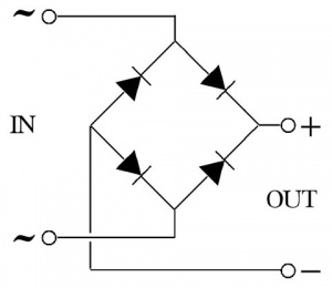
In order for the motor to use the DCC power, the power must be converted to Direct Current. Multifunction decoders use a Diode Matrix (see image) routing the digital signals from both rails to provide power for the decoder. A diode matrix consists of four diodes (a device that lets electricity flow in only one direction) connected in a specific way. In this example, when Rail A is energized the current will flow through one pair of diodes, returning to the booster via Rail B, until Rail B becomes positive and the other pair of diodes conduct. There will be an additional diode in the matrix circuit (not shown) which provides the digital signal to the microcontroller's input.
Without the diode matrix, only the pulses on one rail would be used for power, resulting in lower average voltages available to drive the motor and operate the microcontroller and its peripheral circuits. While the voltage on one rail may be enough for the digital circuit, it would vary in average levels, and may cause the microcontroller to reset at times. The matrix allows current to flow from either rail without causing a short circuit.
You can also use a diode matrix connected between the track and your DMM to measure the DCC voltage on the track using the DCV range. This is called a rectified DC Voltmeter. Remember: You typically lose 0.7V (700 millivolts) through a diode. Factor a loss of 1.4V due to the two diodes completing the matrix circuit.
When used for rectification (converting Alternating Current to Direct Current) this circuit is called a bridge rectifier.


