Measuring Track Voltage
Summary: There are several ways of measuring the voltage on the track when Digital Command Control is used. They range from simple and inexpensive to expensive tools. Measuring track voltage is a different process than one used for analog control systems.
Oscilloscope
The oscilloscope is the best method. Not only can you observe the amplitude of the DCC waveform on the track, you can also visually assess the quality of the signal. A distorted signal will be readily apparent. With the addition of current clamps, the amperage being drawn can also be measured.

While professional bench top 'scopes are not cheap, in recent years low cost scopes with LCD displays and a number of sophisticated functions have appeared below $1000. Some can be found for as little as $500. Tektronix has also entered the budget scope market, with some excellent products. While Tek is known to be one of the best, there are other brands that come close to equaling Tek's reputation. Where Tek scopes excel is their patented input circuitry, which gives far better results than low cost budget scopes.
Of course, there are a number of low cost options available for smart devices. Several "pocket scopes" are on the market which use an iPhone or other device as their display. For DCC measurements, they are adequate, and can often be found for less than $200.
Making Measurements with an Oscilloscope
Using a scope to measure track voltage is rather straightforward. Assuming knowledge of how to use the scope, a 10:1 probe is connected to one rail, and the ground clip onto the other. After a few adjustments, the display will have a trace of the waveform. Most modern devices have built in math functions, so the display will probably include voltages and frequencies present. The 10:1 probe should be trimmed first to ensure you get an accurate trace. The scope should provide a reference signal to trim the probe for the correct wave shape.
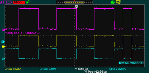
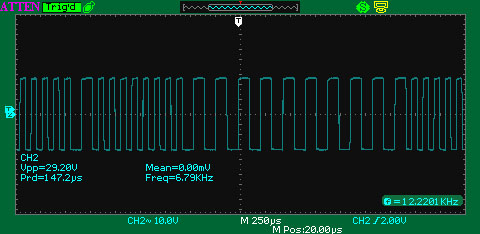
Remember: The scope's zero reference point is floating, as it follows the DCC booster's output state. The trace is misleading as it isn't really 28Vpp, but 14Vp on each rail. This fallacy leads to the belief that the voltage across a gap will be doubled if there is a phase mismatch. [1][2][3]
The above traces can be made by connecting the ground clip to the ground connection on the booster, and the probes to Rail A and Rail B. The scope traces will display each channel in operation, verifying each phase is working, their amplitude and that one rail is in the inverse state of the other. [4]
Voltmeter
- Main article: Digital Multimeter
A simple analog or digital multimeter can be used to measure track voltage. This is a little more involved due to the nature of the DCC signal.
Method 1: Rail to Chassis Ground
The measurements are made between one rail and a common reference point, such as the case of the booster/command station. On a Digitrax booster, there is a "GND" terminal used as the reference.
Use the DC Volts (DCV) mode, on the 20VDC range, if the meter does not autorange.
Ensure that Address 00 (analog) is set to a speed of 0. [5]
Ground refers to the reference point, be it a marked terminal or the case. If measuring to the case, use a bare metal point, such as the head of a screw.
- Measure from Rail A to Ground. Record this value
- Ignore the sign, as DCC has no polarity.
- Measure from Rail B to Ground. Record this value
- The track voltage is the sum of the values found on Rails A and B
This is the method recommended by Digitrax. [6]
NCE
For Power Cab owners, NCE recommends measuring the output of the Power Cab using an AC Voltmeter. The measurement is made at the back of the Power Cab Panel (PCP) and should read approximately 13.8VAC. NCE does caution that getting accurate readings with any meter will be difficult.
| Scale | Recommended Track Voltage |
|---|---|
| Large Scale[7] | 18 |
| O/S/HO | 14 |
| N | 12 |
| Minimum | 7 |
NMRA Recommended Voltages by Scale
The table shows the NMRA recommendations for voltage. There will be some variations in the measured voltage. Other sources may indicate slightly different voltages. Most decoders can handle much more than the nominal voltage before damage occurs.
According to the table, an HO scale layout should have 14V on the track. Using the above method, the readings should be 7V between each rail and the reference point, for a total of 14V. Digitrax recommends 15V, with a tolerance of 0.6V. The manufacturer of your DCC system may have a different recommendation.
List of NMRA Standards related to DCC
Measuring Track Voltage
- Main article: DCC Power
Why Does the Meter Read Half of the Voltage
Good Question.
The reason lies in the periodic nature of the DCC Waveform.
The voltage on the rail switches on and off, creating pulses. The On time is equal to the period the voltage is Off. For an analog DC Voltmeter, this results in only 50% of the torque needed to move the needle. For a digital meter measuring DC Volts, there will be an equal number of samples during the On and Off periods, which when integrated, result in a reading of half the actual voltage.
Example: If the voltage is 20V for 50% of the period, and 0V for the remaining 50%, the average voltage is (20 + 0) ÷ 2 = 10V.
Another limiting factor is Bandwidth. A Digital Multimeter with limited bandwidth cannot accurately measure all the harmonic content of a square wave, resulting in a lower reading. The integrator can also form a low pass filter, rolling off frequencies above its cut-off frequency when measuring non-sinusoidal waveforms.
Why does a Meter on DCV Measure Zero Volts between the Rails?
Again, the answer lies in the periodic nature of the DCC signal.
When measuring voltage between the rails using the DC Volts range, the average voltage is Zero. A DC Voltmeter expects the current to always flow in the same direction. Since the current flows from A to B, then B to A, the rapidly reversing currents seen by the meter do not create enough torque to move the needle, or in the case of a DMM, it is displaying the sum of the two, which is zero. Unlike the AC Volts function, where the current is expected to reverse direction on a periodic basis.
What is the difference between DC and RMS Measurements?
RMS is the DC heating value, allowing direct comparisons between DC and AC measurements. So 12VAC is equivalent to 12VDC, without requiring any computations to compare actual or computed values.
RMS Voltage has the same power content as DC Voltage.[8]
All AC voltages and currents have an RMS value.[8]
RMS Voltage
An RMS Voltage is calculated as follows: Vpk × √2 ÷ 2 = VRMS [8]
- Where Vpk is the maximum voltage reached
- √2 = 1.414
- Another method is to multiply the peak voltage or current by 0.707 (which is 1.414 ÷ 2)
RMS Current
An RMS Current is calculated as follows: Ipk × √2 ÷ 2 = IRMS [8]
- Where Ipk is the maximum (peak) current.
Square Waves
A repetitive symmetrical square consists of a single step change in voltage that alternates between two defined voltages for equal periods of time. The Peak, Average rectified and True RMS values of a symmetrical square wave are the same.
Adjusting the Track Voltage
Should adjustments be necessary, such as matching the amplitudes between boosters, consult the manufacturer of the DCC system.
Notes
- DCC has phase, not polarity. If positive and negative voltages were present on the rail, using the Rail to Chassis method results in a reading of Zero Volts on the DC range.
- Phase is relative: With DCC, one rail is always the inverse of the other: If Rail A is ON, Rail B is OFF.[4]
- When Rail A is ON, current flows from A → B, and when the state of the rails are inverted, A ← B
- Ground does not refer to earth ground, it is just a common reference point for all measurements. Your DCC system floats.
See Also
- DCC Power - Is it DC? Or AC?
- ↑ The DCC track signal is floating, meaning there is no Zero or Ground reference. Many see the waveform and incorrectly assume it is an AC signal with positive and negative values.
- ↑ P = Peak, PP = Peak to Peak. AC values displayed on a meter are in RMS (root-mean-square) values, which is 70.7% of the peak value. Low cost digital meters often measure the average value of an AC waveform and are calibrated to display the RMS value.
- ↑ There will often be claims a Differential Probe is required to measure DCC signals. As the DCC signal is floating, and isolated from earth ground, an expensive accessory such as this, with limited applications, is unnecessary.
- ↑ 4.0 4.1 The DCC signal can be described as bi-stable, meaning it will be in one of two defined states.
- ↑ If Zero Stretching is in use it will shift the average DC value away from 0V, the value it would normally have.
- ↑ Track Voltage Measurement on DCC Layouts with Direct Home Wiring
- ↑ Voltage can be up to 24V.
- ↑ 8.0 8.1 8.2 8.3 Calibration: Philosophy and Practice, 2nd Edition, Fluke Inc.


