Function Mapping
Summary: Remapping functions allows alteration of which outputs are controlled by a function. It can also eliminate multiple key presses to achieve a result.
Function Remapping
Remapping functions can eliminate multiple key presses or key combinations to achieve a result. Fortunately, more manufacturers support remapping in their decoder software. Others have included automation, where activating one function key triggers several functions.
Some functions may offer limited options for remapping, such as F0, F1 and F2 (lights, bell and whistle).
Why Remap Functions?
There are several reasons for remapping a function.
- Standardize functions among different brands of multifunction decoders:
- As OEM will change suppliers of multifunction decoders over time, and may offer different decoders in different locomotive, function remapping can maintain a consistent function key usage over a number of different decoders in the motive power fleet.
- Simplifiy Button Presses
- With the advent of decoders supporting more than ten or twelve functions, the number of keys on the throttle to control them was exceeded. To solve this many DCC manufacturers began adding a shift key functionality to their throttles. Much like a computer keyboard where pressing Control or Control-Shift gives access to alternate characters.
- Unfortunately, that usually means having to press multiple buttons to access F11 or F28. Which can be confusing. In some cases, a key or key combination is needed to access the function. The result is that the full complement of functions is ignored in favour of the bell and whistle
Planning A Function Map
The easiest way to accomplish function remapping is to plan which functions will be assigned to each key in advance, using a spreadsheet. Refer to the manufacturer's instructions to determine what is possible and how the default function map is laid out.
Begin by selecting the functions desired, and the key which they will be mapped to.
The Function Matrix
| CV | Function Description |
Output | |||||||||||||
|---|---|---|---|---|---|---|---|---|---|---|---|---|---|---|---|
| 14 | 13 | 12 | 11 | 10 | 9 | 8 | 7 | 6 | 5 | 4 | 3 | 2 | 1 | ||
| 33 | FL(f) Forward Headlight | 128 | 64 | 32 | 16 | 8 | 4 | 2 | 1 | ||||||
| 34 | FL(r) Reverse Headlight | 128 | 64 | 32 | 16 | 8 | 4 | 2 | 1 | ||||||
| 35 | Function 1 | 128 | 64 | 32 | 16 | 8 | 4 | 2 | 1 | ||||||
| 36 | Function 2 | 128 | 64 | 32 | 16 | 8 | 4 | 2 | 1 | ||||||
| 37 | Function 3 | 128 | 64 | 32 | 16 | 8 | 4 | 2 | 1 | ||||||
| 38 | Function 4 | 128 | 64 | 32 | 16 | 8 | 4 | 2 | 1 | ||||||
| 39 | Function 5 | 128 | 64 | 32 | 16 | 8 | 4 | 2 | 1 | ||||||
| 40 | Function 6 | 128 | 64 | 32 | 16 | 8 | 4 | 2 | 1 | ||||||
| 41 | Function 7 | 128 | 64 | 32 | 16 | 8 | 4 | 2 | 1 | ||||||
| 42 | Function 8 | 128 | 64 | 32 | 16 | 8 | 4 | 2 | 1 | ||||||
| 43 | Function 9 | 128 | 64 | 32 | 16 | 8 | 4 | 2 | 1 | ||||||
| 44 | Function 10 | 128 | 64 | 32 | 16 | 8 | 4 | 2 | 1 | ||||||
| 45 | Function 11 | 128 | 64 | 32 | 16 | 8 | 4 | 2 | 1 | ||||||
| 46 | Function 12 | 128 | 64 | 32 | 16 | 8 | 4 | 2 | 1 | ||||||
Notes:
- The underscored value is the default [1] [2]
- Always consult the manual for the specific decoder in question
- CVs 33 through 37 control outputs 1 through 8, and cannot be remapped outside of that range
- The black areas indicate function outputs that are not available for that range
- While it is possible to move output 4 between F2 and F3, it is not possible to move output 3
- CVs 38 – 41 maps to outputs 4 – 11
- CVs 42 – 45 maps to outputs 7 – 14
Remapping
To remap the function the process is simple. To remap function 4 to function 6:
Referring to the matrix above (or the one supplied with the decoder)
- Determine the value of CV 38 (Function 4). In this example 4.
- Write this value into CV 40
To map multiple outputs to a single function key:
- Map Functions 9 and 12 to Function 9
- Determine the values for F9 and F12
- F9 = 16 and F12 = 128
- The sum of those values is 144
- Change the value of F9 (CV 42) to 144
DecoderPro
With the level of sophistication in multifunction decoders increasing every year, software tools such as DecoderPro make remapping much easier. For ESU multifunction decoders, consider the LokProgrammer as well.
- Examples of Function Mapping using DecoderPro for an ESU Loksound 5
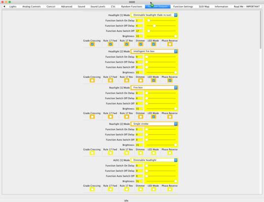
Function Outputs for an ESU Loksound5
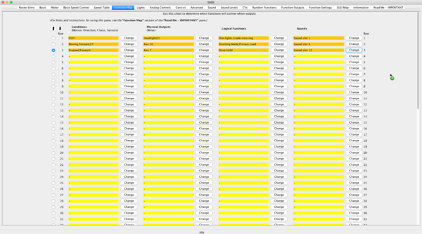
ESU Loksound 5 Function Mapping

