Multifunction Decoder
Summary: Typically installed in vehicles such as locomotives, a Multifunction Decoder controls motor and lighting functions.
Multifunction Decoder Overview
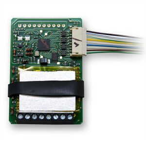
Multifunction Decoders are installed in locomotives and other vehicles. Multifunction decoders receive instructions and in turn control the movement, speed, direction, lights, animation, sound or even uncoupling devices. They are called multifunction decoders since they do more than just control the motor.
Accessory Decoders are used for other purposes, like controlling turnouts or signals They typically offer two states of operation.
How Multifunction Decoders Work
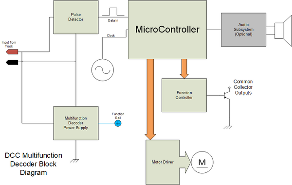
A multifunction decoder receives power and control information via the rails and converts this into motor power, motor control and function(s) control. An explanation of how a decoder converts DCC power to DC power, and delivers it to the model's motor is discussed in the DCC Power article.
A decoder is actually a small computer system. It takes power from the track, in the form of a digital packet. This provides power to operate the decoder, as well as data. When a valid digital packet addressed to it is received the decoder processes then acts on the instructions. Speed and direction information are applied to the motor controller, which supplies voltage to the motor, causing the locomotive to move in the direction desired. The microcontroller can turn on lights, activate them based on direction, as well as allow operation as part of a consist. More advanced decoders have more features, including sound.
Evolution of DCC Multifunction Decoders
Over time, the multifunction decoder has evolved, gaining new features and improving on older ones. This section will concentrate on the motor control aspect of their evolution.
Early Multifunction Decoders
The original multifunction decoders had a primitive Pulse Width Modulation (PWM) scheme using a low frequency to drive the motor. It was very similar to the method used by analog power packs with pulse power. While low speed operations were good, many locomotives had a loud hum created by the PWM signal. The PWM frequency was low in the audio range, from 30 to 200 Hertz. Often this would resonate with the chassis and shell, producing an annoying hum.
High Frequency Drive
The second generation of decoders featured a higher frequency PWM signal, from 15 to 40kHz. This reduced the hum by increasing the drive frequency into a range people can't hear. While this improved the noise issue, and didn't impact slow speed operation, it came at the cost of reduced torque.
Improved High Frequency Drive
Multifunction decoders began to appear with modifications to the high frequency PWM scheme to improve torque. Usually called torque compensation, which was the addition of dithering to the motor drive signal. Dither involves adding low frequency components into the PWM signal so as to add the benefits of the low frequency drive scheme without incurring its drawbacks. Better torque, without the noise issues.
Back Electromotive Force
Back EMF or Back Electromotive Force is a problem with motors. Eddy currents in the rotor are created by the magnetic field as it turns. These limit the top speed of the motor, requiring more power to overcome them.
BEMF can also be put to use. Decoders appeared with the ability to measure the BEMF voltage, and use that to better control the speed. Algorithms in the decoder's firmware use that to maintain a constant motor speed. Additionally, multifunction decoders with sound also use that information to alter the sound based on the motor load. Not only will your train maintain speed travelling up a grade, the locomotive will make sounds indicating it is working hard doing so. Downgrade, it will adjust the sound accordingly, for more realism.
Back EMF with PID
The fifth generation of multifunction decoders added the PID feature. Additional algorithms worked with the BEMF to make small, incremental changes to the motor drive signal. The PID feature tries to match the real values to a desired value by making small but continuous adjustments.
Selecting a Multifunction Decoder
Please see the Multifunction Decoder List for a comparison of multifunction decoders.
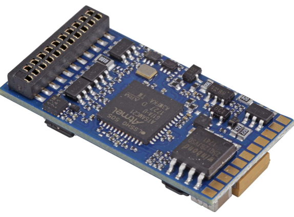
The decoder size will be dictated by the amount of available room inside the locomotive or tender body as well as the amount of current demanded by the motor. There should be enough room for cooling and wiring as well. Before selecting, it's best to determine the stall current of your particular locomotive. One decoder can drive multiple motors, provided the sum of the stall currents doesn't exceed the decoder's current rating.
Another issue is the locomotive interface. If a DCC Ready locomotive has an interface, the easiest way to add a decoder is to purchase one with the matching interface.
The DCCWiki also has a multifunction decoder comparison guide to get you started on selecting a multifunction decoder.
Multifunction Decoder Features
Multifunction decoders have a number of features and functions that vary with the manufacturer, and even the specific decoder model. Don't be alarmed by the large list of features listed. Usually, the defaults that come with today's decoders work well. If the decoder you have has a feature you do not need or want, simply ignore it. We've broken the list down to a few basic areas:
Motor Control Features
Decoders may or may not have features such as Back EMF, Speed Tables, and slow speed controls,
Programming and Addressing
- Addressing: Two and Four Digits - Decoder address, can be two or four digits (in Hex, not Decimal)
- CV Reset - Resets all decoder settings to factory defaults
- Decoder Programming
- Decoder Programming Lock - Helps protect against decoder settings from being accidentally changed.
- Decoder User Values - User defined space - IE: Loco Owner ID. Entering values here doesn't make the decoder operate any differently, but it does make it possible to tell two identical locomotives apart.
Lighting and Effects (Functions)
- Directional Lighting - also usually provides individual control of headlights. Part of CV29.
- Function Re-mapping - changes what function button a function responds to.
- FX Lighting - Special lighting modes - requires programming CVs greater than 100. Available effects differ from one manufacturer to another. See your specific decoder specifications.
- Master Light Switch - Turn all functions off with one operation.
Sound File Customization
Some sound decoders allow the user to load or modify existing sound files. This will usually require dedicated hardware and software to perform these functions. Others may also permit extensive changes to the way the decoder operates.
Miscellaneous Features
- Short-Circuit Protection - Protects the decoder against incorrect wiring when first turned on
- Thermal Protection - Protects the decoder against heat damage if the decoder is overloaded or overheated
- Transponding - Only Digitrax has this feature. It is not part of the NMRA DCC Standard
- RailCom - An optional method of data transmission between the locomotive and the command station.
- Asymmetric DCC - Offers simple automation on decoders with this feature.
- RailCom - A transponding system developed by Lenz and offered by many European DCC brands.
- Automatic Brake Control
- Asymmetric DCC
Functions
- Main article: Functions
Functions are solid state control circuits on decoders that control lights, sounds, smoke, animation, uncoupling devices, etc. Many are not limited to simple on/off functions - for example, some lighting functions are capable of imitating MARS lights, Gyralights, Rule 17 dimming, single or double flashing strobes, ditch lights, and other effects. Many decoder lighting outputs are 12 volts DC. Other decoders are specific to certain models, and still others have built-in voltage regulators or resistors for LEDs. Always check your decoder's documentation to verify output levels before you install lighting.
There are currently 29 functions, F0-F28. Most DCC systems now support 29 functions, while some may still only support 13, F0-12. Older systems may support less.
Decoder Installation
- Main article: Decoder installation
All multifunction decoder installations include the following steps:
- Select a decoder that fits inside the body shell and has space for wiring
- Does it have the required current rating for the motor
- Isolate the motor from the track pickups
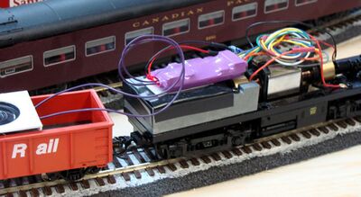
- Install the decoder along with wiring for any extra effects
- Test the completed installation.
Multifunction Decoder Testers
There are decoder testers available from several companies for testing decoders. Programming is also possible before installation. The decoder cannot be installed in a locomotive when using a decoder tester.
Many commercial units include a speaker, LEDs for the functions and a motor, allowing a complete test of the decoder prior to installation or programming. Basic programming can be done on the workbench, and final tweaks applied after installation.
Power Source Notes
DCC Decoders are designed to operate on a DCC layout. Operation on an analog layout does have risks, as do the use of DIY DCC boosters.
Analog Operations
Some decoders can be destroyed when operated on an analog layout. Some analog power packs can create spikes which permanently damage the decoder.
See the warning from Rapido Trains regarding analog operations and decoder damage for more information.
Homebrew DCC Systems and Power Supplies
It is possible for homemade analog supplies or DCC Boosters to damage decoders. Analog DC supplies may introduce voltage spikes which can damage a multifunction decoder. Improperly designed or constructed DIY DCC Boosters can introduce a DC voltage to the track that can damage a DCC Decoder.
- It is best to only use DCC systems which meet the NMRA DCC Standards to operate locomotives with DCC decoders installed, to avoid damage.
Low Cost Decoders
Be aware that some low-cost decoders are available on the market which use pirated software. They have been marketed and sold in hobby shops under various brand names. Often, they can be found on online auction sites. If the price of a decoder is notably less than the cost of a typical equivalent, be aware that it may be a counterfeit. Parts of questionable quality may be used as well, and support can and will disappear quickly when the fraud is discovered. The victims in this are small DCC companies designing and writing software for their decoders.
Remember: If they were willing to cheat someone to create the product, there is no reason they will not cheat you too.
