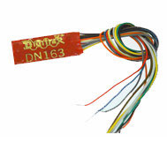
Hardwired Multifunction Decoder
Summary: A Hardwired Decoder is used when a locomotive is not DCC-ready and does not have a plug or a drop-in replacement DCC control board. The decoder must be soldered directly to the rail pickups and the motor terminals.
Wired Multifunction Decoders
Unlike plug in multifunction decoders, which use a plug and socket for ease of installation, hardwired decoders have a harness consisting of wires which must be soldered to various connections in the locomotive during installation. After installation the wires must be cut or desoldered to remove the decoder for replacement.
Though there is no strict standard for hardwired multifunction decoders, they usually closely follow the wiring conventions for 8 Pin DCC Plugs. It is also possible to solder the wires to an 8 Pin adaptor for use with a vehicle which has an 8 pin female socket.
A decoder with a JST Connector is similar to a hardwired decoder because the connector only interfaces between the decoder and its harness, the other end of the harness must still be soldered directly to the locomotive's pickups and motor terminals.
Connections
| Orange | Motor Right | Connect to the motor terminal that was previously connected to the right rail |
| Grey | Motor Left | Connect to the motor terminal that was previously connected to the left rail |
| Black | Left Rail | Connect to the left rail pickup |
| Red | Right Rail | Connect to the right rail pickup |
| Blue | Common (Positive) | Connect to the Positive (Anode) side of all the functions (lights, etc.) |
| White | Front Headlight (F0) | Connect to the negative side of the front headlight |
|---|---|---|
| Yellow | Rear Headlight (F0) | Connect to the negative side of the rear headlight |
| Green | Function 1 (F1) | Connect to the negative side of the function 1 device |
| Violet | Function 2 (F2) | Connect to the negative side of the function 2 device |
| OR | ||
| Brown | Function 2 (F2) | Connect to the negative side of the function 2 device |
Notes
The Blue "common" wire does not connect to the frame! It is common to the various function lines. It connects to the Anode (A) or positive terminal of an LED. The decoder follows the "common cathode convention" used with digital logic.
- The series resistor used with an LED can be installed on the Anode or Cathode. The cathode (K) is connected to the desired function wire.
- If installing multiple LEDs for various light functions, use multiple series resistors, one for each LED. While this requires more space for the installation, it prevents an issue where if one LED fails, additional current will now flow through the remaining LEDs connected to the one common series resistor, causing them to fail in time.
For decoders with more function outputs there may be additional wires and there may be violet and brown wires for two different functions (F2 and F3).
Both motor terminals and all functions must be fully isolated from the rail pickups before installation.
The negative and positive sides of the headlights and functions are important if the devices are polarity sensitive, such as LEDs.
