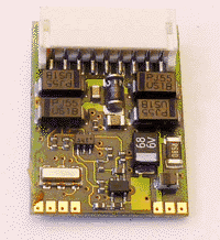
JST Connector
Summary: JST is the name of the manufacturer, which makes many connectors. Be aware that many on-line sellers often describe these connectors by incorrect names, perpetuating confusion of the exact type and style of connector. These types of connectors are very popular with drone and Radio Control Aircraft hobbyists.
A JST Connector is a mechanism to connect a Multifunction Decoder to its wiring harness. This means the decoder is removable and replaceable without any further soldering. The 9 pin version of this connector is covered by the NMRA standard.
JST refers to the component manufacturer, Japan Solderless Terminal Manufacturing Co. Ltd., of Japan, maker of the plugs and sockets used in these applications. The NMRA Standards refer to the JST part number for the socket as S9B-ZR-SM2-TF.
Installing a decoder with this socket is similar to installing a Hardwired Decoder because the other end of the harness must still be soldered directly to the locomotive's pickups and motor terminals.
Connections
Connections as per NMRA S–9.1.1.2
| Pin No. | Purpose | Colour (S–9.1.1.2) |
|---|---|---|
| 1 | Output 3 (Aux 1) | Green |
| 2 | Track – Right Rail | Red |
| 3 | Motor (+) | Orange |
| 4 | Common (+V) | Blue |
| 5 | Output 1 (Front Headlight) | White |
| 6 | Output 2 (Rear Headlight) | Yellow |
| 7 | Motor (–) | Gray |
| 8 | Track – Left Rail | Black |
| 9 | Output 4 (Aux 2) | Violet or Brown |
- Previously some manufacturers used brown or violet prior to a defined Standard colour. Pin 9 can be violet or brown, the manufacturer must document it in their installation instructions.
Previous Colour Coding
| Pin | Purpose | Connection | |
|---|---|---|---|
| 1 | Violet or Brown | Function 2 (F2) | Connect to the negative (cathode) connection of the function 2 device |
| 2 | Black | Left Rail | Connect to the left rail pickup |
| 3 | Grey | Motor Left | Connect to the motor terminal that was previously connected to the left rail |
| 4 | Yellow | Rear Headlight (F0) | Connect to rear headlight |
| 5 | White | Front Headlight (F0) | Connect to the negative side of the front headlight |
| 6 | Blue | Common | Common connection to the positive (or anode) side of all the functions (lights, etc.) |
| 7 | Orange | Motor Right | Connect to the motor terminal that was previously connected to the right rail |
| 8 | Red | Right Rail | Connect to the right rail pickup |
| 9 | Green | Function 1 (F1) | Connect to the negative side of the function 1 device |
- Both motor terminals and all functions must be fully isolated from the rail pickups before installation.
- The negative and positive sides of the headlight and functions are important if the devices are polarity sensitive, such as LEDs.
- Multifunction Decoders follow the Open Collector convention used in digital electronics. The Anode is the common connection.


