LED Lighting and Resistors
Summary: Light-Emitting Diodes (LEDs) are solid state light emitting devices known for their low current draw and long lifespan. LEDS are ideal for use with multifunction and function decoders.
A Light Emitting Diode is a semiconductor light source which emits light when there is electron flow through it. The colour depends on the semiconductor materials used to manufacture the diode. White light can be produced by using multiple semiconductors or a layer of light emitting phosphor applied to the device.
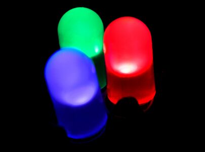
Blue, green and red LEDs.
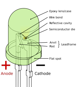
Construction details
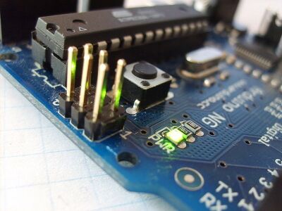
An SMT LED, useful in tight spaces and for ditch lights
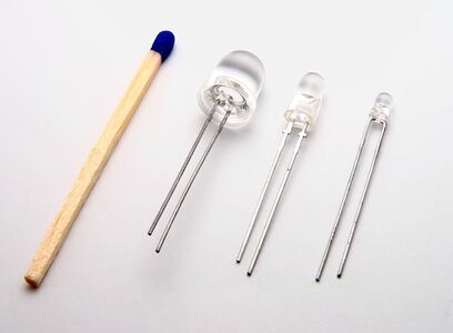
A variety of LEDs with a clear lenses. Tamiya Clear Yellow paint can simulate an incandescent lamp when applied to a white LED

.svg.png)


Practical LEDs were introduced in the early 1960s, eventually appearing in consumer electronics. The early visible light LEDs were low intensity and only available in red, often used to replace indicator lamps or in a seven-segment display such as those used in early handheld calculators or digital watches.[1]
LEDs have a number of advantages over incandescent lighting. They are robust, produce less heat, can be made in smaller sizes and consume less energy. They also have a much longer lifespan than an incandescent light bulb[2]
One large advantage: They emit more light per watt of energy.

Light Emitting Diodes
An LED is a diode; therefore current can only flow through it in one direction[3]. A common application is replacement of lamps or additional lighting effects. While LEDs are available in a variety of sizes and colours, white LEDs do not look like incandescent lamps. The preferred colour is Sunny White. It is also possible to tint the lens of a white LED to get the correct effect.
Light Emitting Diodes and Series Resistors

An LED is a current controlled device. In most applications related to Digital Command Control, a simple, low-cost resistor is used to limit the current flowing through the LED. For more exacting applications a controlled current source would be used instead of a resistor.
The LED is a semiconductor device that will burn out quite quickly when its specifications are exceeded.
Protecting an LED from Reverse Voltages
If you plan to use an LED for applications which will require connecting it to track voltage, it must be protected from Reverse Voltages, usually called PIV . PIV may also be called Peak Reverse Voltage. In the case of the DCC track signal, the cathode will become positive while the anode is grounded. LEDs are susceptible to damage in cases like this, as their maximum reverse voltages are usually less than DCC track voltage.
Applications would include indicators on a panel showing turnout alignment.
To protect the LED, there are two possible solutions. Both cases involve the addition of another diode in parallel, but reversed.
- A small signal diode, which will limit the PIV to less than a volt
- Another LED, such as a red one, preferred as they have a lower Forward Voltage (VFWD), especially compared to a "white" LED
The protection diode is wired across the LED, and is in series with the resistor. This prevents it from appearing as a short.
How Much Series Resistance is Required?
- Main article: Ohm's Law
The following explains how to wire LEDs for your model train or layout without letting the magic smoke out of the LED.
Unless stated otherwise in the multifunction decoder's instructions, the Common or Blue lead supplies +12V. Use this value when calculating the necessary series resistance.
LEDs are current devices, as the current increases (series resistance decreasing) the LED will emit more light. Increasing the series resistance reduces the current and will dim the output of the LED
In this example, our LED specifies a forward current of 20mA (milliAmps) at a forward voltage of 2 Volts. We will be wiring the LED from a power source, and using a resistor to limit both the current and the voltage. (Always read the spec sheet for your LED as it will have the details you need to calculate the series resistor.)
Voltage from one end of a string of devices in series (like the LED and Resistor, above) to the other is divided among the items in the series, in proportion to their resistance. Assume that the voltage source is 9 Volts DC. Since the voltage across both devices is 9 Volts, and the LED is rated for 2 volts, the voltage drop across the series resistor must be 7 volts.
Since the current through two devices in series is the same, the desired maximum current through the LED is 20 mA, then the voltage across the resistor must be 7 volts at a current of 20mA. The value of the resistor will be calculated using those two values.
Ohm's Law

We need to calculate the value of the resistor. Ohm's law tells us how Voltage, Current, and Resistance in a circuit are related. The 3 variables are:
- Voltage (measured in Volts, represented by the letter V, or it may be E or U). [4]
- Current (measured in Amperes, represented by the letter I ('eye')) [5]
- Resistance (measured in Ohms, represented by the letter R or the symbol Ω)
Multipliers
Resistance values are often expressed as a value with a multiplier.
- milli (m) is 1/1000th
- kilo (k) is a thousand
- Mega (M) is a million
- Note the difference in case between prefixes m and M.
Instead of writing 0.05A, it will be 50mA. A 47,000Ω resistor will be identified as 47kΩ.
Formulae
The law says that V = I × R. This can be re-arranged to say I = V ÷ R or R = V ÷ I. This 3rd form is the one we want:
- Resistance = Voltage ÷ Current
So, we have following information about our LED circuit:
- LED, Forward Current: 20mA, Forward Voltage: 2V
- The 20mA is important, if exceeded the LED will be destroyed.
- Power supply: 9VDC
- The Forward Voltage (VFWD) must not be exceeded, so the series resistor must have a VDrop of 7V
- Resistor value is an unknown
The math:
- R = (Vpower supply – VFWD) ÷ IFwd
- R = (9 – 2) Volts ÷ 20 milliAmps
- R = 7 Volts ÷ 0.020 Amps
- R = 350 Ω (Ohms).
The next step is to choose a resistor with a value of at least 350Ω. (This value written as 350R.)

Resistors are manufactured in standard values. Standard values near 350 Ω include 330, 360, and 390 Ω. Due to manufacturing processes, resistors are manufactured with 5, 10, or 20% tolerance. The tolerance means the value may vary ±5%, 10% or 20% from the stated value. Many of the resistors you see today will be 10% or better tolerance, as the carbon resistors are no longer manufactured[6] Carbon resistors are much larger and often brown in colour. (See the table below for the Standard Values).
Erring on the side of caution, the preferred value for the series resistor would be 390Ω.
With a manufacturing tolerance of 10%, a 390Ω resistor could range from 351 to 429Ω. If the value is precisely as marked, a 390 Ω resistor would limit the current to 7/390, or 18mA. This is below the 20mA maximum for the LED. At the lower extreme (assuming a worst-case value of 351 Ω) the maximum current would be 20mA.

Ratings for a LED are the MAXIMUM values! Limiting the current to less than 20 mA or reducing the voltage will extend the life of the LED, just as running a light bulb at less than rated voltage will extend its life. Additionally, as in a light bulb, reducing the current or voltage will reduce the brightness of the LED. Although an LED is much less sensitive to changes in current.
Often when a power supply is not supplying a full load, the rated output voltage is exceeded! Calculate the resistance based on a higher than rated voltage, and a lower than rated current.
Resistors in Series and Parallel
Series

Total Resistance equals the sum of the resistances.
Parallel

The total resistance of resistors connected in parallel is the reciprocal of the sum of the reciprocals of the individual resistors.
1/(1/R1 + 1/R2 … + 1/Rn)
Quick Tip: The total resistance of resistors in parallel will be less than that of the lowest value resistor.
Wiring Multiple LEDs
When wiring multiple LEDs in a circuit, it is preferred to connect them in parallel, each with its own series resistor to limit the current. In this case, the power source must be able to supply enough current in total to ensure each device gets enough current. Ten LEDs at 20mA each would need a total current of 200mA.
Large numbers of LEDs can be powered by a lower current power source by multiplexing them. Each LED is rapidly switched ON, then OFF, but to the human eye, it appears to be constantly lit. For the additional complexity of the driver circuits, a larger power supply is simpler.
Why Not Use a Single Resistor for Multiple LEDs?
One can, but one really should not.
Example:
- Ten LEDs in parallel, 20mA IFWD. VFWD is 2V.
- Power source is 12V.
There are two components to this circuit:
- Ten LEDs in parallel, VDrop = 2V, ILED = 20mA × 10 = 200mA
- Series Resistance: VDrop = 10V, IResistor = 200mA.
Ohms Law says RSeries = V ÷ I: 10 ÷ 0.2 = 50Ω
Should one LED fail, the current flowing through RSeries will still be 200mA to maintain the 10V drop. ILED is now 200 ÷ 9, or 22.2mA.
Not all LEDs are alike. Some may flow more current, others less. So one might be flowing 25mA, until it fails. Now you have 8 LEDs remaining, flowing on average 25mA. When another fails, it becomes 29mA...
LED Parameters IFWD and VFWD are nominal, not absolute values for a specific LED. These values vary by batch, and by individual LED.
Dimming an LED
Reducing the light output of an LED can be accomplished in two ways: Increasing the series resistance to reduce the forward current, or by use of Pulse Width Modulation. LEDs powered by a PWM signal may appear to flicker or flash when photographed.
Identifying the Anode and Cathode

Identifying the Anode (A) and Cathode (K) can be easy with some LEDs. The typical LED with the coaxial leads has a flat spot on the package, and a shorter lead, which is the cathode. The positive lead (Anode) is the longer lead.
Another technique is to hold the device up to the light so you can see the internal structure. The cathode (or anvil) looks like a flag.
Surface Mount Devices


Surface Mount Devices (or Surface Mount Technology) are very small components. By eliminating most of the packaging, the component can often be made smaller, which means less cost for packaging it, and higher board density at manufacture. SMD/SMT LEDs can be used in tight spaces. They may or may not come with leads. It is possible to solder wires onto an SMD LED, which will require something to hold it in place during soldering. Double sided tape works, or an adhesive material that will not become permanent.
To identify the K (cathode), there may be a stripe (like a diode), a dot, or a chamfer on one corner of the package. If not, there may be a dot printed on the underside of the package. As always, consult the data sheet for the device if you are unsure.
Another type may look like a little button, with three leads, two long ones and a short one, with a hole. The two long leads are the anode and cathode. The short lead, or tab with the hole, is part of the lead frame. The lead opposite it is the cathode. The lead next to the tab is the anode. As always, check the data sheet.
Why is the Cathode marked with a K?
The terms Anode and Cathode go back to the vacuum tube diode. The Anode is the positive connection which is in turn connected to the B+ power supply connection. The Cathode was usually grounded, and marked as K on schematics. The K was used, as C was already claimed to indicate a capacitor on a schematic. The term C- referred to the control grid voltages used in an amplifier.
Handling LEDs
While LEDs are rugged devices, there are some precautions when handling them.
- Do not flex the leads. If they need to be bent, use pliers to support the leads between the bend and the LED package. This minimizes the stress at the point where the lead enters the package.
- This is also a best practice for other leaded electronic components. The result is more workman like and prevents accidental damage.
- During soldering, use heatsinks to prevent overheating the device. If soldering on SMD LEDs, secure the LED and work fast.
Failure Modes
The most common LED failure mode is the gradual reduction in light output and loss of efficiency. However, sudden failures can occur. When operated at, or just below their rated current (i.e. 20mA) an LED should last 100,000 or more hours before failure.
Other failure modes include:
- Extreme Current - Excessive current will let the magic smoke out of the LED, causing premature failure.
- Extreme Heat - Caution should be used when soldering LEDS to a board or wires to its leads. A soldering heat sink is recommended.
- Electrostatic Discharge - ESD may cause immediate failure of the semiconductor junction. Be sure to ground oneself, the workstation and use an ESD safe soldering iron when working on any electronics.
- Excessive Reverse Voltage - LEDs can be very intolerant of excessive reverse voltage. Diodes are designed to withstand a reverse voltage, and have a PRV (Peak Reverse Voltage) specified. LEDs are not designed to be used as rectifiers, with a much lower PIV.
Avoid the excessive current failure vector by using a resistor for each LED. This prevents increasing current if one LED fails, since a single resistor is calculated to limit the current with multiple LEDs connected to it. Two LEDs connected in parallel with one series resistor will flow 40mA of current, and the resistor will be half the size. Meaning it will allow 40mA through one LED should the other fail. See the above section on Ohm's Law.
LED Colours
The colour of a LED is important.
The first LEDs were Red in colour. Later, Green and Yellow LEDs appeared. For a number years, those were the only colours available, with Blue ones eventually appearing, and later still, White
For the examples below, a 5mm commodity LED is the norm for values presented. Always check the data sheet as values can vary.
RED LEDs
Red, Red-Orange, and Orange LEDs are typically 1.7 to 2.4V at 10mA.
Green LEDs
Green, and yellow-green, are typically 1.8 to 2.4V. Some green LEDs can be 3 to 3/5V.
Blue LEDs
2.8 to 3.5V. Early "blue LEDs" were in fact, small incandescent lamps with a blue diffuser. Later ones were true semiconductors and further development brought blue LEDs five times brighter than their predecessors.
White LEDs
White light can be created by two methods: Multiple semiconductor diodes on the same die, or a white light emitting phosphor coating, like that of a fluorescent light. Most use the phosphor coating method. Typical V FWD is 3 to 5V.
White does not appear in the colour spectrum as it is not a colour; instead, perceiving white requires a mixture of wavelengths. A trick is employed to make white LEDs: Blue-emitting semiconductor base material is covered with a converter material that emits yellow light when stimulated by the blue light, similar to a fluorescent light's construction. The result is a mixture of blue and yellow light that is perceived by the eye as white.[7] Newer white LED developments have used multiple LED light sources on the same die
White LEDs exhibit a colour shift due to different concentrations of converter material, in addition to a change of wavelength with forward voltage for the blue-emitting InGaN material. So when changing the forward current, the colour balance of the LED with shift. This can be an issue if multiple LEDs are used. Also, dimming the LED will have some effect.
LEDs can be tinted using a paint such as Tamiya Acrylic X-26 Clear Orange to act as a filter. Simply apply the paint to the "lens" portion of the LED's epoxy packaging. The LED is sealed so the paint cannot get inside.
Reading the Data Sheet
Manufacturers and distributors of LEDs will supply a data sheet outlining their products parameters. There are a number of details you need to know. (These were taken from a Vishay white LED data sheet.)
Parameters
Forward Voltage indicates the amount of voltage drop across the junction, which must not be exceeded.
| Forward Voltage | ||
|---|---|---|
| V | ||
| Min | Typ | Max |
| 2.8 | - | 3.6 |
| Maximum Ratings | ||||
|---|---|---|---|---|
| Parameter | Test Conditions | Symbol | Value | Unit |
| Reverse Voltage | VR | 5 | v | |
| DC Forward Current | IF | 30 | mA | |
| Soldering Temperature | t≤ 5s | TSD | 260 | °C |
Two details are important: VR and IF. The maximum current, IF must not exceed 30 mA, and the maximum reverse voltage VR applied to the LED is 5V.
What the Data Sheet Reveals
As seen in the tables above, the maximum current is 30mA, and forward voltage is 3.6 MAX. For easy calculations, a nominal VF of 3.0V will be used.
Calculation Example
Power supply, VS will be 14V.
The forward voltage is 3V. Therefore, the series resistor must flow enough current to develop a potential across it of 14 − 3 = 11V.
Using the value of 11V, Ohms Law says that R = V ÷ I, or 14 ÷ 0.03, which is 467Ω. Resistor values in this range are multiples of 4.3, 4.7, and 5.1. Using that rule, 470Ω is a reasonable choice, at a tolerance of 5% or ±24Ω. Since a lower value will cause more current to flow, the better choice is 510Ω, which results in a current of 22mA. This also gives a margin of safety.
Standard Resistor Values
- Main article: Table of Standard Resistor Values
Reading a Resistor's Value
Resistors are marked with four colour coded bands. They read from left to right, with the band closest to the end being the first value. There may be additional bands to indicate tolerance and other parameters.
| RESISTOR COLOUR CODE | |||
|---|---|---|---|
| COLOUR | DCCWIKI.COM | ||
| VALUE | MULTIPLIER | TOL, % | |
| BLACK | 0 | 1 | |
| BROWN | 1 | 10 | 1 |
| RED | 2 | 100 | 2 |
| ORANGE | 3 | 1000 | |
| YELLOW | 4 | 10K | |
| GREEN | 5 | 100K | |
| BLUE | 6 | 1M | |
| VIOLET | 7 | ||
| GRAY | 8 | ||
| WHITE | 9 | ||
| GOLD | 0.1 | 5 | |
| SILVER | 0.01 | 10 | |
No tolerance band, the value is 20%. With advanced manufacturing and better resistor materials, 20% is rare today, most resistors are in the 5 to 10% tolerance range. Older carbon composite resistors are 20%, but are no longer used, as they can change value from stresses and suffer from moisture induced changes to their stated value.

Decoding the Resistor Colour Code

Reading a resistor's colour code is not difficult. Always align the bands so the gap between the bands is to the right. The band after the gap is the tolerance.
The multiplier is 10x, where x = the value of that band. For example, a Red band indicates a value of 2, so 102 = 100. A blue band is 106, or 1 with six zeros following, meaning multiply by 1,000,000 (a MegOhm).
Four Band plus Tolerance
A resistor with four colour bands having a value of 1000 ohms would be Brown, Black, Black, Brown. Which is 1, 0, 0, or 100, times 10. A 42kOhm resistor would be Yellow, Red, Black, Red, or 420 × 100, = 42000 ohms. There will be a gap with a fifth band following, which is the tolerance. A typical resistor has a silver band, or 10% tolerance.
Three Bands, plus Tolerance

Many resistors have three bands instead of four, in which case 42kOhm is Yellow, Red, Orange, or 42 × 1000. In these resistors there is no decimal point.
Another resistor with 3 bands, Brown, Red, Blue = 12MOhms (12 × 106). If the multiplier were Green, it would be 12 × 105, or 1.2MΩ.
It is unlikely that a resistor with a gold or silver multiplier will be seen.
Surface Mount Devices
Reading a Surface Mount (SMD/SMT) resistor:
Surface mounted resistors of larger sizes (metric 1608 and above) are printed with numerical values in a code related to that used on axial resistors. Standard-tolerance surface-mount technology (SMT) 5% resistors are marked with a three-digit code, in which the first two digits are the first two significant digits of the value and the third digit is the power of ten (the number of zeroes). For example:
- 334 = 33 × 104 = 330 kΩ (33 × 10,000)
- 222 = 22 × 102 = 2.2 kΩ (22 × 100)
- 473 = 47 × 103 = 47 kΩ (47 × 1000)
- 105 = 10 × 105 = 1 MΩ (10 × 100,000)
Resistances less than 100 Ω are written: 100, 220, 470. The final zero represents ten to the power zero, which is 1. For example:
- 100 = 10 × 1 = 10 Ω (100 = 1)
- 220 = 22 × 1 = 22 Ω
Sometimes these values are marked as 10 or 22 to prevent a mistake.
Resistances less than 10 Ω have 'R' to indicate the position of the decimal point (radix point). For example:
- 4R7 = 4.7 Ω
- R300 = 0.30 Ω
- 0R22 = 0.22 Ω
- 0R01 = 0.01 Ω
Precision resistors are marked with a four-digit code, in which the first three digits are the significant figures and the fourth is the power of ten. For example:
- 1001 = 100 × 1 = 100 Ω
- 4992 = 499 × 100 = 49900Ω
- 1000 = 100 × 1 = 100 Ω
000 and 0000 sometimes appear as values on surface-mount zero-ohm links, since these have (approximately) zero resistance. Precision resistors are also marked with an alphanumeric code, where a table is used to find the value.
More recent surface-mount resistors are too small, physically, to permit practical markings to be applied.
(From Wikipedia)
Video: Surface Mount LEDs for Model Locomotive Lighting
See Also
External Links
- GUIDE TO LED CIRCUIT DESIGNS AND LED BASICS & OPERATION
- Also see this website for more information: SM LEDs.
- All About LEDs
- LED Colors & Materials
- The Forward Voltages of Different LEDs
- LEDs at the Electronics Club
- ↑ Superseded quickly by Liquid Crystal Displays (LCD), which require less energy in battery powered applications.
- ↑ The incandescent light wastes much of its energy producing infrared light and heat.
- ↑ Unlike a regular diode, LEDs will not tolerate large reverse voltages. Excessive reverse voltages (PIV) will lead to an early failure.
- ↑ V, named after the Italian physicist Volta, E = Electromotive Force, or U, from the German word for Potential.
- ↑ It comes from French: Intensité.
- ↑ Carbon resistors are still available for specialty applications. In general usage, metal film resistors are much cheaper and offer better tolerances.
- ↑ The mixing of specific colour values is the principle behind colour television.