Inrush Current
Summary: Inrush or Surge currents are sudden current drawn by a device when first switched on. This surge in current will only last a few cycles of the input power until it returns to a normal state. Often caused by energy storage devices used with multifunction decoders.
Inrush current, input surge current, or switch-on surge is the maximal instantaneous current drawn by an electrical device when first turned on. Alternating-current electric motors and transformers may draw several times their normal full-load current when first energized, for a few cycles of the input waveform. The selection of over-current-protection devices such as fuses and circuit breakers is made more complicated when high inrush currents must be tolerated. The over-current protection must react quickly to overload or short circuit faults but must not interrupt the circuit when the (usually harmless) inrush current flows.
Causes
A discharged or partially charged capacitor appears as a short circuit to the source when the source voltage is higher than the potential across the capacitor. A fully discharged capacitor requires at time of 5RC. This determines the rate of charge/discharge, known as the Time Constant. Five-time constants are required for a full charge/discharge. </ref> time cycles to fully charge; during the charging portion of the cycle, instantaneous current can exceed typical load current by a substantial multiple. In the case of an open circuit, the capacitor will be charged to the peak AC voltage (one cannot actually charge a capacitor with AC line power – this refers to unidirectional alternating voltage output from a rectifier).
In the case of charging a capacitor from a linear DC voltage, such as that supplied by the diode matrix onboard a multifunction decoder, the capacitor will still appear as a short circuit; it will draw current from the source limited only by the internal resistance of the source and ESR of the capacitor. In this case, the charging current will be continuous and decline exponentially to the load current.
As shown in the graphs, the capacitive current declines while the voltage across the capacitor increases over time.
See Managing Inductance for more information on bus wiring and impedance.
Energy Storage Circuits
Energy storage circuits such as those used in multifunction decoders appear as a short to the booster when power is first applied to the track. The surge currents will charge those capacitors, with the only impedance of the track bus and the ESR of the capacitor limiting the rate of charge.
The capacitors require 5 time constants to fully charge. A Time Constant is defined at Resistance × Capacitance, in seconds. One time constant represents 63% of charge. For example, with a 5A source, the first-time constant is 63% of 5 or 3.2A, the next time constant is 63% of (5-3.2) or 1.1A. This change continues until 100% of charge is reached.
As many boosters use rate of change to detect a potential short circuit, this rapid surge in current causes the booster's overcurrent protection circuits to react.
Booster Issues
Often the booster will interpret the sudden surge in current as evidence of a short circuit. It will react by cutting off the power, then restoring it after a short period of time has elapsed. Since the burden causing the surge hasn't been fully charged, the cycle will repeat endlessly.
Most boosters have a low impedance output, offering little resistance to limit the surge current.
Usually with one or two locomotives equipped with an energy storage device this isn't an issue, but as more similarly equipped locomotives are added to the equation, it will become a problem.
Solutions
Additional Impedance
Additional impedance must be added to the circuit prior to switching on, and removed after the initial surge has dissipated. As mentioned previously, the addition of impedance to the circuit limits the surge currents.
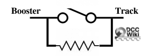
A SPST could be used to insert a resistor in the off (open) position and short across it in the on position. A few seconds after applying track power the switch would be changed to "ON", shorting out the resistor.
This is simple to accomplish, simply solder a resistor between the two terminals. Experimentation will be needed to find a resistor value that works, and the time required. A 5Ω, 20W resistor is a good starting value. Any value under 100Ω should suffice. A 50Ω, 2W resistor will also work.
A relay can be substituted for the toggle switch, controlled remotely by a switch or a timer circuit.
Engine Storage Tracks
Another possibility is adding the ability to control power to engine storage tracks using a switch. By turning off power to the track(s) and energizing them later as needed, the inrush current can be reduced to acceptable levels. Another solution would be the addition of DPDT toggle switches with resistors in parallel to isolate the track completely. The switch can either isolate the track, allow the capacitors to charge, then the track can be brought into full operation when needed. The wiring is similar to that of the SPDT, with the resistor between the poles, and the wiper connecting the booster to either pole. If the DPDT has a center off position, the track can be isolated as well.
Commercial Solutions
These devices may or may not work, depending on the situation.
Tam Valley TurnOn Module
Tam Valley offers a module (TRN001) that inserts a load into the circuit when the track power is switched on, then disconnects after a few seconds, throttling the surge currents to avoid a nuisance trip. It is connected to the booster's track outputs before any other devices. It will work with up to 3A of surge current.
DCC-LSP Surge Protector
This device from DCCconcepts attempts to dampen surges to prevent annoying short circuit issues when many locomotives are on the track during power-up. It can also help with other track issues causing current spikes which trigger the overcurrent protection feature of the booster.


