Wiring for Digital Command Control (DCC)

DCCWiki, a community DCC encyclopedia.
(Redirected from Wiring)
Jump to: navigation, search

Summary: Wiring for DCC is not as complicated as some would have you believe, but it is a very important component to the entire Digital Command Control Experience. Good wiring is essential for reliable operation with Digital Command Control. Due to the large number of related topics to wiring, this article is meant as a jumping off point to other articles. Brief summaries of each topic, with a link to the primary article for more detailed information. Whether you are starting your first layout or converting an existing layout, this is a good place to start.

Wiring For DCC
Wiring-SimpleLoop30dpi.png

Wiring Your Railroad for DCC

All the manufacturers make the same claim: Just two wires to the track and you are ready to go! Reading the manual, it says something much different. It talks of buses, feeders, and the distance between feeders. The need for a power bus made of heavy gauge wires. Did they not tell you that wiring for Digital Command Control was much simpler? Going to your favourite online Model Railroading Forums you ask if all this wiring recommended by the manuals is necessary.

You will get many answers, some will be conflicting or provide erroneous information. Some will say yes, you need all that wiring. Inevitably someone will say the opposite, claiming they run their entire layout with a pair of wires from the booster to the track and nothing else. Maybe someone referred you here to the DCCWiki.

Which answer is right and which is wrong?

Yes, you can use two wires to connect the command station/booster to the track. Should you? No.

Wiring is extremely important for reliable DCC operation and signal integrity. Digital Command Control is not Analog DC, and the wiring practices for analog operations do not apply here. You just can't crack open the throttle a little more when the train slows down, because DCC allows you to operate your trains, instead of your focus being on controlling the track voltage.

The following pages explain DCC wiring concepts, methods and best practices. So, you control your trains, not the track.

Dcs52.jpg

General Wiring Topics

  • Wiring Tools – First things first. You'll need some basic tools. Some simple electrical tools can be made for a few dollars that can save you hours of time and less frustration while wiring your layout. Keep in mind that you do not buy tools, you invest in them.
  • Wiring Complexity – Wiring for your layout can be as simple or as complex as needed or desired.
  • Wiring Color Code – It's best to develop a colour code when you're just getting started. However, it's important to stick to it! This article explains picking a wire colour code as well as wire sourcing to help you stick to your code.
  • Wire Sizes and Spacing – Are these wire sizes overkill? How far apart should the track feeders be? Answers to these, and more.
  • Wire Types – Selecting the correct type of wire is important for the reliability of the DCC signal on the track.
  • Voltage Drop – Model railroads have low tolerance for voltage drops throughout the layout. Be sure to use the proper wire gauge and feeder spacing.
  • Do I Need to Twist the Bus Wires? The question everyone asks.
  • Wiring Tips and Tricks
  • Soldering Yes, there is soldering!

Track Wiring

  • Wiring Your Layout The approach you'll take will depend on what type of project you are attempting. This page is intended to steer you in the right direction.
  • Block detection – Block detection is a method for detecting rolling stock within a given section of track with the use of Accessory Decoders
  • No Common Rail Wiring – In wiring for DC (analog) operations, modellers usually had one wire which was common to all blocks, the rail it connected to was not gapped over the entire layout. Do not do this for DCC!
  • Reverse sections – Although the electrical phase on the rails does not control the direction of the loco, you still have to deal with reverse sections on your layout. If the track turns around back onto itself, the right rail will come in contact with the left rail, which will cause a short circuit; the same as placing a metal object across the rails.
  • Turntables – Wiring Turntables
  • Turnouts – Wiring Turnouts. For Digital Command Control things are a little different. What to look for, selecting turnouts, and other topics.
  • Crossings – Wiring Crossings, Single and Double slips
  • Crossovers and Slips – Wiring Single, Double and Scissor Crossovers.
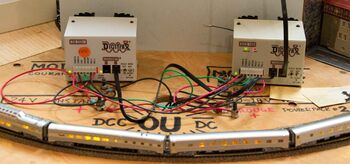
Boosters-Module.jpg

HMContoller.jpg

Conversion from Analog to Digital Command Control

See Converting to DCC for more information.

Important: Conversion to Digital Command Control involves upgrading the wiring to Digital Command Control's requirements. If the plan is to convert to Digital Command Control in the future, wire the layout for Digital Command Control from the beginning.

  • Lenz manufactured a device designed to protect equipment when Direct Current (analog) was used on the layout at the same time as your Digital Command Control system. This device, the LT100 Digital Circuit Breaker, was wired in series with your analog throttle. One LT100 was required per throttle. The device disconnected analog power to that block when a Digital Command Control decoder equipped locomotive crossed the gap. Otherwise, a short would occur and damage would follow. Once the entire locomotive was in the block, the Digital Command Control signal was disconnected and the analog throttle took over, for seamless operations. As many modellers have completely embraced Digital Command Control, Lenz no longer offers the LT100 Digital Circuit Breaker. Read the manual for the LT100 here.
  • If CV 29 is set correctly for Alternate Power Sources, a multifunction decoder should work on direct current. The danger of setting a decoder for alternate power sources is possible loss of control. On a layout that can be powered by Digital Command Control or Direct Current (by disconnecting one power source and connecting another) all the locomotives can suddenly accelerate if the throttle and block switches are not set correctly and direct current is applied to the tracks. Many modellers set the decoder to NMRA Digital Command Control Only operation to prevent a runaway should the decoder encounter a corrupted Digital Command Control signal and switch to Analog operation.
  • Some analog power packs with a pulse power mode can damage or destroy a DCC multifunction decoder. Other decoders may behave erratically.

Further Reading