Power Management
Summary: Power management is important for operations. Breaking up your layout into separate power districts prevents a short circuit in one area of your layout bringing the entire layout to a halt.
Power management is implemented using an electronic device connected between the track power bus and the booster. This device can use either electronic or mechanical means to connect/disconnect the track from the bus. They operate as a circuit breaker, disconnecting the power from that power district when an event occurs to trigger operation. Some can be user configured for trip points and reaction speed.
What Is a Power District?
Booster and Power Districts
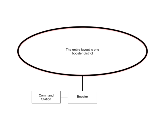
A Layout with One Booster Powering the Entire Layout
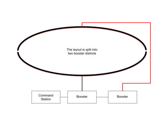
Layout with Two Booster Districts
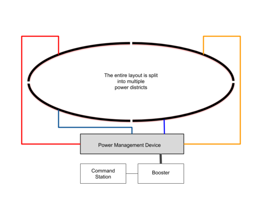
Layout with Four Power Districts


Hierarchy
The method of organizing your layout wiring is pyramid, with the booster at the apex:
- Booster
- Power Manager
- Auto-Reversers
- Track Bus
Below booster is a power management device, which splits the feed from the booster into two or more, for feeding the power districts. These also function as circuit breakers, which will act before the booster does, prevent an unplanned event in one district shutting down the entire layout.
Other devices, such as additional circuit breakers or auto-reverse/phase inversion devices, are at the next level, below the power manager. They must be configured to act before any circuit breakers upstream. The final level is the track bus for that district.
Some devices will not function correctly when connected to an upstream circuit breaker. These must connect to the booster directly, forming their own independent power district.
Booster District
- Main article: Power District
A Booster District indicates a section of trackage supplied by a single booster. If the layout has only one booster, the entire layout would be a booster district. If the trackage is split into two electrically isolated sections and directly supplied by individual boosters, the sections would be referred to as Booster Districts.
For some DCC systems, it is advisable to install a circuit breaker on their booster output, as this is lacking in the booster. In this instance the result would still be a booster district.
Under no circumstances should two boosters power the same section of track.
Power District
- Main article: Power District
Remember: For correct operation of a power management device, such as a circuit breaker, it must be set to trip at a lower current than that of the booster supplying it. Refer to their manuals on how to adjust trip points and reaction times for both the booster and the circuit breaker.
Power Districts: Multiple isolated track sections fed by a single booster through a power management device. This results in subdividing a booster district into several power districts supplied by that booster.
Think of power districts as being similar to the way a building is wired. For this example, the main breaker would be the booster, and the load center is the equivalent to a power management device. Power comes into the building from the utility. It passes through the main breaker and then into the load center. The load center has multiple fuses or circuit breakers, which divide the building's wiring into multiple circuits. This is for safety and convenience. Overloading a circuit trips the breaker, but the entire house doesn't go dark. For safety purposes the breakers in the load center are much lower capacity than the main breaker, limiting the amount of current needed to trip.
Analog Operations: Blocks
With Analog DC layouts the track sections are isolated from other sections and fed electricity independently. The term used to describe these sections is a block. The cab is connected to the layout, and selector switches are used to connect the cab to a specific block. As the train progresses, blocks are activated and deactivated by the operator. The electrical routing is usually configured such that only one cab can control a section of track, or block. It is possible to have two selector switches, one which selects the cab, the second the track block. On larger layouts (such as a club) a dispatcher may control the cabs and block activation using a large control panel and track schematic.
In this scenario, the operator is controlling the track, not the train. Should another operator change the selector switch's position to his cab, he would now control the track and any trains on it.
In Digital Command Control the same idea is implemented differently, and the term for a block is power district. Many operators can be in control of trains in the same "block" or power district.
The difference between analog and DCC is analog layouts have multiple low current power supplies instead of a single high current power source. The cab is inserted between the power supply and the track, and often is confined to a small local section of the total layout. This simplifies wiring by eliminating the need to run large bundles of wire between a central power supply and multiple cab connection points and trackage.
Products
To be effective, the circuit breaker must trip at a current below that of the booster's output.


- Digitrax BXPA1 Power Manager, transponding and auto-reverser.
- Digitrax PM42: Adjustable from 1.5 to 12A
- OnGuard OG-CB: 4A Max (Not adjustable.)
- NCE
- EB-1: 2.5 to 8A
- NCE does not recommend usage of the EB-1 with a PowerCab or Digitrax Zephyr Starter Set. NCE recommends the CP-6 Circuit Protector.
- EB3
- CP6 (Power Cab Only)
- EB-1: 2.5 to 8A
- Tam Valley DFJ Circuit Breaker: Two- or Four-Amp trip point selectable
- CVP Zone Share: Up to Four Amps
- DCC Specialties PSX Power Shield X: Up to 17A. [1]
- Voltscooter Automatic Fuse: 0.8 to 3.8A (via jumpers).
Notes
Timing Issues
Timing can be an issue with power management devices. Ensure the trip current settings of the booster are at their maximum so the downstream device can act first. It defeats the purpose of power management when the booster trips first and disconnects all the power districts connect to it.
PSX
The PSX-AR will not reliably operate when installed after a PSX circuit breaker. The PSX-AR has an auto reverser, it must be powered directly by a booster for reliable operation.
See Also
- Track wiring - Page on Track Wiring
- Auto Reverse - Auto reverse devices
- Short Circuit
- Power District
- Power Shield X
References
- ↑ See warning regarding PSX-AR timing issues.