Installing LEDs with DCC Decoders
Summary: A series of technical notes outlines how to use Light Emitting Diodes (LED) in place of incandescent lamps.

Thanks to Don Fiehman for drafting these handy tips for using Light Emitting Diodes with Digital Command Control.
This series of Tech Notes is designed to help modellers with DCC Multifunction Decoder installation. This note covers using LEDs (Light Emitting Diodes) with DCC Multifunction Decoders and for signalling.
Also see the LED Lighting and Resistors page for more information.
Why Light Emitting Diodes?

When installing lighting in a locomotive you have a choice of either incandescent lamps or solid state Light Emitting Diodes. There are reasons to choose one over the other. Factors to consider are life, cost, size and ease of installation. Incandescent lamps have been with us for a long time. Light Emitting Diodes are newer and the technology of LEDs is changing for the better.
The first visible light emitted by Light Emitting Diodes was red in colour, followed later by yellow and then green. In recent years white LEDs have also become available. The first white LEDs had a blueish tint that did not look like an incandescent locomotive headlight. Recently the Golden-White, Yeloglo and Sunny-White LEDs have changed this. These new LEDs produce colors that are closer to that of an incandescent lamp. These new LEDs are now installed in some new locomotives supplied with some Multifunction Decoders and available through many model railroad suppliers. The cost of LEDs is just a bit more than lamps, but well worth it over time. When installed correctly an LED will outlast the locomotive.

LEDs are available in different sizes. They run from the jumbo at 10 mm in diameter to a very small “chip” size (known as surface mount devices) that mounts on circuit boards.
The common sizes are 3 and 5 mm. The 3 mm is the best choice for HO headlights. LEDs are available in range of colours: Red, green, yellow, blue and white are the common colours. The LEDs that are made to resemble the yellow-white appearance of an incandescent lamp are the Golden-White, Sunny-White and Yeloglo.
The Golden-White is made with an amber colour epoxy that filters out some of the blue light. OK when on, but shows the amber colour when off. The Sunny-White and Yeloglo LEDs have the incandescent appearance when lighted and clear when off.
Lamps versus LEDs
The LED has many advantages over incandescent lamps. LEDs have a life expectancy rated in years, not hours for a lamp. LEDs are much more efficient at producing light. Lamps produce heat and some light, LEDs produce light and some heat! The light output from a LED is much less sensitive to changes in voltage and current than an incandescent lamp. The maximum current rating of most LEDs is 20 mA (milliamps). The light output from a LED is almost constant from about 5 mA to the maximum (about 20 mA).
Please note – although many LEDs are designed as shown in the diagram below, be sure to check the specifications for your LED before making connections!
Multifunction Decoder LED Setting
Some multifunction decoders have a CV setting for LEDs. This does not mean that the output will be changed for use with an LED, a resistor will be required.
The purpose is to ramp the current up or down, simulating an incandescent lamp. LEDs are unrealistic when they instantly light, compared to an incandescent lamp where the brightness increases as the filament heats up.
LEDs Require the Correct Polarity
.svg.png)
Note that the Cathode (negative lead) is next to the flat spot on the package, and if you hold it up to the light, the cathode is the large element that looks like an anvil. The Anode (positive lead) has the longer lead.
The light from a lamp is not focused and is good for passenger cars and buildings. When installed in a locomotive they put out some light through the headlight and in many cases end up also lighting the interior of the cab. LEDs produce a beam of light like a flashlight. This is why they work so well in LED flashlights. This is also why LEDs work so well for headlights, signals and panel indicators. In a darkened layout room, an LED headlight can light up the area in front of the locomotive like a prototype headlight.
One problem with LEDs is they do not respond the same as lamps. LEDs turn on and off almost instantly. Lamp filaments must heat up and cool off. This does not affect their use as a headlight or strobe light, but LEDs behave differently when dimmed or used with special lighting effects. The response of the LED versus a lamp may not be satisfactory with things like dimming and Mars lights.
LEDs are semiconductors, in fact they are a specially made diode. At some point, they will just switch off as the voltage and current is reduced. A certain level of energy is needed to begin and maintain conduction through the diode.
To compensate for these differences when using special lighting effects many of the newer Multifunction Decoders have provisions to let it know it is operating an LED. This is typically a bit in a CV (configuration variable) that controls the special lighting. When set, this bit changes the output characteristic to match the LEDs. This lets the LED appear to response like an incandescent lamp. I checked one of these Multifunction Decoders and found that for “Rule 17" dimming the power was reduced to under 10% for the LED and only 35% for a lamp.
Wiring LEDs

The LED is a Light Emitting Diode, and as a diode, polarity must be observed when it is installed. The electrical schematic above shows the standard schematic symbol for an LED: the Anode, Cathode and emitted photons (the tiny arrows). The arrowhead is the Anode(A), the bar is the Cathode (K), and when operating, the anode is more positive than the cathode so the arrowhead shows the direction of conventional current flow when the LED is illuminated.
Multifunction Decoders have a common connection, the BLUE wire, which provides a common connection (open collector) for all the function outputs. It is connected the Anode of an LED.

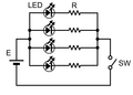
LED connections series
LED connections parallel
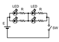
LED connections mixed


Open Collector Outputs
This is an advanced topic.

The Function Outputs use a transistor wired as an Open Collector. When that transistor is turned on, current can flow through the transistor as it is acting as a switch.
Note: Digital logic has the convention where inputs are in fact a source, and outputs are sinks. Using an open collector is a simple way switching the output from "open circuit" to closed, allowing the output to sink current supplied by the input of another device. Yes, it is backwards, but that is how it works.
Multifunction Decoders use open collector outputs for LED / Incandescent lighting and other functions. The blue wire supplies VCC[1] to the Anode (positive connection) of the LED, and the cathode connects to the output. When the transistor is switched on, current can flow from VCC to circuit common via the LED (and its series resistor), causing it to light.
Wiring LEDs Without the Blue Common Connection
The blue wire is used to supply Vcc to the LEDs used in a vehicle. Some multifunction decoders, particularly those using a 6 or 8 pin connection, may lack the ability to add extra functions.
If the decoder has additional accessible Fn connections, usually in the form of a solder pad, it is possible to add additional functions, thanks to the Common Collector connections within the decoder.
This is accomplished by making a connection to one rail pickup. Many manufacturers simplify their wiring by using the frame to complete the circuit, much like that of an automobile. In this case an ohmmeter should record a value of zero Ohms between one rail and the frame. If that is true, the frame can be used to supply VCC to a function. If not, a connection to one rail must be directly made via one of the pickups. Do not use both as this will create a short.[2]
This method works when the frame (or the selected rail) becomes energized, supplying VCC, current flows through a LED or lamp, returning to the track via the decoder's internal wiring. The light output will be less as the supply rail alternates between the High and Low states of the DCC data stream. When the rail is low there is no potential voltage between the frame/pickup and the decoder.[3]
Further Reading
What does “open collector” mean?
LEDs and Resistors
A series resistor is needed for each LED connected to a function output. Its purpose is to limit the LED's current to a safe value. The resistor value is selected to limit the current to a safe amount, while creating a voltage drop. The voltage drop is needed to prevent the diode from burning out when voltage in excess of its VFWD is applied across the diode. Different color LEDs present slightly different voltage drops (VFWD) across the leads of the device, in most cases those differences can be ignored. Unlike lamps that require you to select a value of resistor to match the lamp, selection for LEDs is easy. Without the series resistor to limit the current passing through it, the LED burns out in a flash.
If the resistance is too low, the LED burns out, if it is too high, the LED will not illuminate. But luckily, the range between "too low" and "too high" is quite broad. And unlike incandescent lamps, an LED's brightness is relatively insensitive to current variations. Between "too low" and "too high", altering the resistor value will have little effect on the LED's brightness.
A 1kOhm (1000 Ohm) 1/4 Watt resistor works fine with 10 to 14 volts on the rails. If using more than the standard 14 volts use a 1/2 watt 1K resistor. If space is at a premium even a 1.5K Ohm 1/8 Watt resistor will work. Up to 3K can be if the LED is too bright.
- See Ohm's Law.
- See also LED Lighting and Resistors for a generic example.
If you have two LEDs that will be controlled by the same function the LEDs can be wired in series and share the same resistor. LEDs work better in series than in parallel because the same current flows through both LEDs. I have used up to 3 LEDs in series with a 1K resistor. (Two red for rear markers and one white for a headlight.) The resistor can be connected to either of the LED's leads. Wiring a number of LEDs in parallel with one current limiting resistor is a bad idea: If one LED fails, the current through the others will increase, leading to their failure.
When soldering wires to an LED use a heat sink between the LED and the solder joint. A heat sink can be a long nose pliers with a rubber band around the handles. The rubber band will keep the pliers closed and sink the heat before it gets to the LED. As with all semiconductor devices, heat can destroy them. Hint: If you are using heat shrink tubing on the wiring, slide the tubing over the wires before making the connection.
Unlike an incandescent lamp, a LED does not generate much heat. This simplifies installation in a plastic body shell. The LED can be mounted directly to the plastic body shell without fear of damage to the shell due to heat from the LED.
Signals and Indicators
Another application for LEDs is signals and as panel indicators (annunciators). Colours used for signals are green, yellow, red and in some cases even blue. Over 30 years ago I installed many coloured lamps in a control panel. LEDs were new, but I did install a few in the panel. I also used bicolor LEDs for searchlight signals. The coating on many of the lamps has faded over the years, but the LEDs are a bright as the day they were installed. In control panels the 5mm works best for me. For signals the 3mm size works best in HO. A series resistor is needed in series with the LED in most applications, The 1k resistor should work for 6 to 14 Volts DC.
The bicolor green-red LED not only produces a nice green and red color by switching the polarity for a searchlight signal, but can also produce yellow. Yellow is made by turning on both the red and green LEDs. To accomplish this alternating voltage (AC) is fed to the LED. The eye will be tricked into looking like yellow.
You can also use a bicolor LED to monitor the status of the track power. Normally it is a yellow/amber, a distinct red or green indicates a DC output bias and may be indication of a malfunction.
Further Reading
- ↑ Voltage Common Collector, a positive voltage applied to the collector of a transistor.
- ↑ Using both pickups is possible with additional circuitry.
- ↑ A multifunction decoder uses a diode matrix internally to route the pulses and create the VCC and required circuit ground/return path (0V) for powering various components of the decoder. This is equivalent to a full-wave DC supply.