DCC Power
Summary: Digital Command Control delivers both power and data in the same signal. Binary data encoded in the signal can be read by the decoder, and the signal also provides power to the decoder.
|
|
Learning how DCC power and control signals work is a very technical discussion. Fortunately, you don't need to fully understand how it works to have a successful and enjoyable DCC-controlled layout. If you're just starting, start with How DCC works first. |
| This page in a nutshell: Power from the Power Supply is combined with control signals from the Command Station and is applied to the layout. Inside locomotives are decoders which can process the requested commands as well as extract power to be used to perform the requested action. Additionally, accessory decoders around the layout (such as switches, railroad crossings, lights, etc) can also be controlled through the same method. |

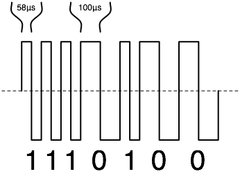
NMRA Digital Command Control, unlike other analog and digital Command Control systems, puts a 100% Digital Signal onto the rails, delivering power and data in the same signal. The digital information is encoded in the time domain using the leading edges of unipolar pulses, not amplitude. It is not superimposed on a DC or AC waveform, nor does it use a high frequency carrier, unlike past and current command control systems. Since the rails are alternately energized or held to zero, there are no issues with polarity.
As the signal is completely digital, the NMRA Digital Command Control [2] waveform is a square wave. The nature of a square wave results in more demanding requirements for wiring to avoid voltage losses and signal distortion compared to analog control methods.
Too Long Didn't Read (TLDR)
There are too many myths surrounding Digital Command Control. Most result from the application of analog ideas to a digital concept. Some from literal interpretations of the NMRA DCC Standards. Others have been promoted over the years due to misunderstandings or dislike for the DCC technology. A prominent source is the application of incorrect terminology.
- The booster supplies a binary 1 (HIGH) / 0 (LOW) signal to the power bus, which is carried to the track, then the train.
- The pulse widths are asymmetrical; the amplitude is symmetrical.
- The DCC signal does not use Pulse Width Modulation. There are only two valid values, not multiple values, as the data is in binary form.
- The binary value is determined by the period from one HIGH state to the next: 106µs (58 + 58) has a value of One, 200µS is a Zero.
- The data is encoded in the time domain. Rise times and the amplitude of the signal carry no information.
- There is full power on the rails at all times while the booster output is turned on.
- Voltage (amplitude) does not determine locomotive speed.
- There is a signal phase present on the rails, where one rail is energized (HIGH/ON) while the other is LOW/OFF. One rail will always be in the opposite (inverted) logical state compared to the other.
- The phase of the rails does NOT control the direction of the locomotive.
- There is no polarity, there are only two possible states: HIGH or LOW. There are no negative voltages present.
- Current flows from HIGH to LOW.
- The rails are identified as A and B, whose phase can be handled by auto reversers when A meets B in a reverse loop, without need to flip toggle switches.
- The DCC Signal is in the audio range. There are no high frequency carriers in the Megahertz region.
- Each output of the booster can be a Source or a Sink, their status is controlled by the data signal from the command station.
The DCC Signal
The Command Station
The Command Station (often called the Headquarters in Europe) is the central component to a Digital Command Control system. Like a train station, everything passes through it.
It features a throttle network, allowing it to connect to various remote devices. Throttles communicate with the command station through the throttle network. When a communication is received by the command station, it evaluates it, then formats a DCC Packet containing the destination and instruction. This is then passed on to the Booster, which amplifies the signal and applies it to the track. The booster may be integrated with the command station, or an external device connected via the throttle network.
The Booster
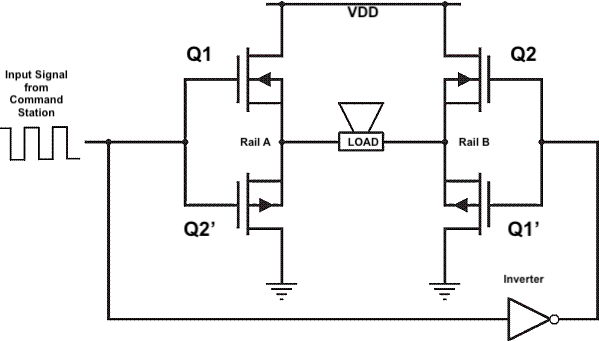
The booster is a digital amplifier. It receives a logic level waveform from the command station. Logic level signals have two states: HIGH or LOW. This logic level voltage is amplified to the necessary track voltage determined by the scale of your model trains. On the track the binary value is determined by the period (time) between the leading edges of the pulses
Amplification is performed by two complementary pairs (Qx and Qx') of MOSFETs [3][4], one on the left side and the other on the right, functioning as switches. When the digital input is low, one pair is switched on to create a path for current to flow (Source to Sink) though the power bus and return to the power supply. When the input signal changes to the high state, this pair turns off and the other pair turns on.[5]
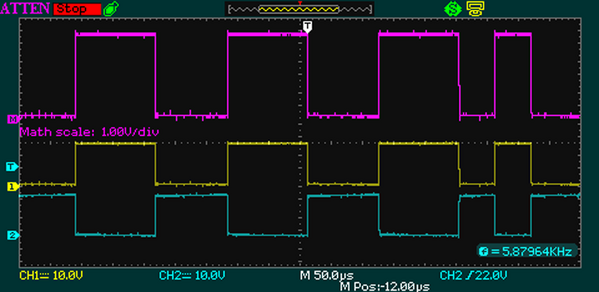
The oscilloscope traces show each pair of FETs in action, and the resulting signal across the rails. The signal across the rails is a floating measurement.[6]
| DCC Track Signal Generation using an H-Bridge | DCCWiki.com | |||||
|---|---|---|---|---|---|---|
| Inverter Input | Device State | Rail Voltage | ||||
| (From Command Station) | Conducting | Non-Conducting | Rail A | Rail B | ||
| High | Q1 | Q1' | Q2 | Q2' | VDD[7] | 0V |
| Low | Q2 | Q2' | Q1 | Q1' | 0V | VDD |
Power
Power is a measure of energy. Energy is required by the multifunction decoder to operate the motor and lighting functions, as well as any other features it has. This power is delivered to the track by the booster.
The amount of power a DCC system can deliver is determined by the capacity of the both the booster and the power supply. An undersized power supply will limit the amount of power available. For N scale, the amount of power needed is low, from 36 to 60 Watts. For HO it can range from 50 to 80W. With larger current boosters, HO can reach 125W, and with larger scales, 240W.
Analog control systems rely on multiple small power supplies delivering low power to the track, such as 12 to 15W. The potential for damage when a short circuit occurs is limited, unlike a DCC booster which can deliver 5 or more amps into a short. For proper operation DCC requires more robust wiring (the power bus) than analog direct current, both for delivery of energy to the decoder, and quick reaction to a short circuit condition.
Voltage
- Main article: DCC Track Voltages
Different scales use different voltage levels. Generally, DCC layouts operate between 10 to 24 volts. See DCC Track Voltages for further details.
Current Requirements
- Main article: Choosing a power supply
The amount of current required is determined by two parameters: The maximum amount of current the booster itself can deliver before overheating, and the current the power supply can deliver. Ideally the power supply should at least match the booster's current handling capacity. A power supply with a lower current output will work. [8]
Of those two parameters, the booster limits the maximum current can be delivered to the track. The booster will also have the capacity to disconnect its output from the power bus should a short circuit occur, to protect itself from damage caused by excessive heat.
Many boosters use Rate of Change to detect an abnormal condition, triggering it to cut off current. This enables a rapid response to a short circuit/overload condition regardless of the actual current flow. Which results in the booster being very sensitive to short circuits, compared to analog power supplies.
Powering a Decoder
As the DCC Signal combines intelligence with power to operate decoders, how is the decoder powered?
Every decoder needs power, and multifunction and function decoders have no means to connect to an external power supply as an accessory decoder would. This issue is solved by the inclusion of a diode matrix in its power supply. The matrix routes the pulses from both rails in the manner required to create a DC Voltage, while also providing a return path for the current to flow back to the booster.
This power is used to power the decoder's microcontroller and supply a positive voltage for the Function Common wire. Most importantly, in a multifunction decoder it provides the voltage and current needed to operate the motor driver circuit.
Signals on the Power Bus
- Main article: DCC Bus Signals
Track Polarity
Unlike analog (DC) where polarity of the track controls the direction of the train, direction is controlled by the multifunction decoder in the locomotive. The decoder receives its speed and direction instructions from the throttle via the command station and acts accordingly. Physically re-orienting the locomotive has no effect.
Digital Command Control has no concept of polarity, as the signals are unipolar. Binary signals do not have the concept of negative. A negative voltage would be considered an Undefined Value. The only possible values are determined by the presence or absence of voltage. The track voltage on an oscilloscope's display indicates the presence of a plus/minus signal. It "sees" a negative voltage because the reference point is floating, as the 0V reference now has a voltage applied to it, with the probe at 0V.[9]
The track voltage has phase, one rail is always the inverse of the other. Phase is an issue with reverse loops and crossovers. A short circuit occurs during a phase mismatch, as current can now directly return to the power source. As mentioned above, the booster output has two pairs of transistors, or switches, each pair consists of a switch which connects the load to the power source, the other allows the current to return to the power source, completing the circuit. The state of these pairs is constantly changing in step with the data signal from the command station.
There are numerous claims that the DCC track signal has positive and negative values, yet this would only be possible if:
- The power supply, with two wires, has an output voltage of at least twice that of the apparent peak track voltage, for example 30VDC at 5A
- The power supply has three wires supplying both positive and negative voltages with a common return/reference point (15VDC / 0 / –15VDC)
- True, the booster could have a voltage doubler incorporated into its design. That adds cost and complexity with no real advantage.
Summary:
- Unipolar, High/Low binary signal, where one rail's state will always be the inverse of the other.
- It is not an analog waveform, where frequency, phase or amplitude have meaning.
- The DCC signal does not incorporate Pulse Width Modulation. Only two values are transmitted, represented by the period between the leading edges.
- There are no Frequency, Phase or Amplitude modulated carrier signals present, at audible or higher frequencies.
- The leading edge's rise time does not carry data.
NMRA Definition of the Positive Rail
The NMRA defines the Positive Rail as the right hand rail when the locomotive is facing forward. [10] The actual direction of travel is determined by the multifunction decoder. This convention maintains compatibility when a multifunction decoder is operated in Analog Mode. [11]
Reverse Loops
When operating with analog (DC), the mainline's relationship to the loop is changed to prevent a short upon exit. With DCC the loop's phase relationship to the mainline is altered. This reversal has no effect on the direction of travel, unlike that of analog controlled trains.
Many argue polarity is the reason reverse loops introduce problems.
The reverse loop is not the problem, the issue lies with the turnout at the entry/exit point. The turnout must have its point[12] and stock rails isolated from the loop. As the train exits the loop, the stock and point rail's phase relationship is reversed with respect to the loop, creating a short. A mechanical or electronic switch controls the phase relationship of the loop [13] with respect to the entry / exit point of the loop. Automatic Phase Inversion devices monitor and correct the phase relationship as required.
Reading the DCC Data by a Decoder
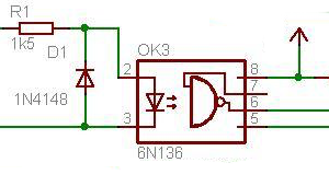
The input circuit for a multifunction decoder consists of an opto-isolator, with a "freewheeling" diode protecting it from a reverse bias condition. This simple circuit allows the vehicle to face either direction while providing a usable data signal to the multifunction decoder.
A more complex input circuit will allow a multifunction decoder to compare the amplitude of the pulses on both rails, known as Asymmetric DCC. Decoders supporting this feature allow additional automation of train operation.
Digital Command Control Signals
- Main article: Digital Packet
Advanced DCC Power Topics
The Advanced DCC Power Topics are provided for information purposes. It is not necessary to understand these topics to enjoy Digital Command Control
NMRA Digital Command Control Standards
The DCC protocol is the subject of two standards published by the NMRA:
- S-9.1 specifies the electrical standard, and
- S-9.2 specifies the communications standard.
Several Recommended Practices documents are also available.[14]
See Also
- DCC Tutorial (Power) - The tutorial version of this document.
- Power supply - Details, requirements, and recommendations for power supplies.
- Root Mean Square - Root Mean Square or RMS, additional information (lots of math).
- DCC Ammeter: What you need to build an ammeter that can measure DCC current. Plus other electronics projects for DCC.
- H-Bridges – the Basics
References
- ↑ This measurement is floating, as there is no reference to a common circuit ground. Images such as this reinforce the myth that DCC is an AC Waveform.
- ↑ https://www.nmra.org/sites/default/files/standards/sandrp/pdf/s-9.1_electrical_standards_2020.pdf
- ↑ Metal Oxide Semiconductor Field Effect Transistor, often abbreviated to MOSFET or FET
- ↑ These are usually integrated into a single IC package, rather than using four discrete devices and their supporting circuitry.
- ↑ These FETs are unique in that one type is turned on by applying a voltage to its gate terminal, while the other is on when there is no voltage applied to its gate. Using two complimentary pairs enables construction of an H Bridge.
- ↑ Floating indicates the measurement lacks a fixed 0 Volt reference point.
- ↑ VDD represents the recommended track voltage. When the transistor is on, full track voltage will be applied to that rail.
- ↑ It may also interfere with the booster's short circuit protection.
- ↑ There is no common reference point held to a zero potential. Another way to look at this is how the current is flowing: It will flow from A to B, then B to A. The scope trace will display this.
- ↑ S 9.2: Forward in this case is in the direction of the front of the locomotive, as observed from the engineer's position within the locomotive.
- ↑ See Alternate Power Source
- ↑ The point rails form the frog in conjunction with the wing rails
- ↑ Phase relationships are maintained by reversing the connections to the track
- ↑ S-9.1 Read the entire document and any notes. The standard is deliberately not specific, as it only describes what the result should look like, not the exact construction. Also note it does not define polarity, as that is a quality wherein the direction the locomotive defines the positive rail.


