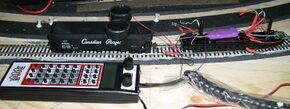
Athearn Genesis With Tsunami TSU-1000
Summary: This article deals with replacing the OEM decoder (supplied by MRC) with a Tsunami Heavy Steam decoder from Soundtraxx.
The user should download and read all the Tsunami documentation supplied by SoundTraxx, as there is more info there than in the included instructions.
| See more Decoder Installs | |
|---|---|

| |
| General information | |
| Original Author | User:Terminator |
| Scale | HO |
| Est. Install Time | |
| Date Installed | 2007 |
| Decoder Product | TSU-1000 |
| Installed Into Product | Athearn Big Boy |
| Keywords | |
ATHEARN GENESIS 'BIG BOY' and TSUNAMI TSU-1000
|
See the Video. |
Tender Disassembly
Remove the body from the chassis, referring to the Athearn instruction manual. Begin with the toolbox. The coal pile must be carefully removed, and there are screws hidden under the water hatches. There is a lot of disassembly.
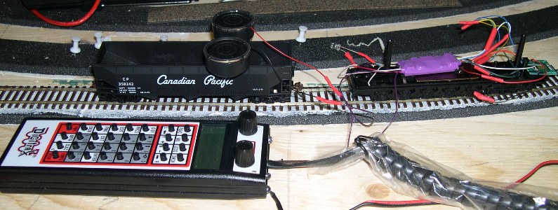
The speaker assembly uses a small plug to connect to the decoder.
Interface
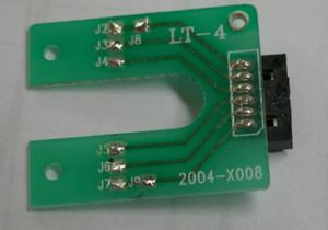
The DCC decoder is connected to the locomotive by a plug and six wires. The female receptacle is mounted on a small PCB attached to the chassis. The decoder wires are soldered to pads on the PCB.
The PCB is labelled as follows: (Functions are in brackets)
- J2/J8 (Red wire, tender pickup)
- J3 (Motor)
- J4 (LED Anode)
- J5 (LED Cathode)
- J6 (Motor)
- J7/J9 (Black wire, tender pickup)
The underside of the OEM MRC decoder has labelled pads indicating the functions.
The TSU-1000 is connected as follows:
- J2/J8, RED
- J3 Grey
- J4 Blue (Function Common bus.)
- J5 White (Headlight LED cathode)
- J6 Orange
- J7/J9 BLACK
The speaker is connected by cutting off the small plug, and connecting the RED wire to Speaker +, PURPLE, and the black wire to Speaker −, PURPLE. See the TSU-1000 Instructions for which purple wire is the positive lead.
The reverse lamp can either be salvaged from the MRC decoder's daughterboard, or a new LED can be installed, with a 680R resistor in series with the cathode. The cathode/resistor is connected to the yellow wire. The cathode can be identified by the shorter lead on the device. The cathode can also be determined by the flat spot on the package, and the rather large internal structure.
The headlight uses the white wire from the decoder. Refer to the Tsunami supporting documentation for complete details on the wires and their functions.
Use heat shrink tubing as needed to insulate any connections. It can also be used to group wires.
- Always test the decoder installation before reassembling the tender!
The decoder should be secured so it cannot damage the speaker cones above it. Wires should be routed in a way that minimizes any interference with the speakers. Be careful not to pinch wires during reassembly.
Troubleshooting
It may be necessary to reset the TSU-1000, and modify a few CV values (such as F0) to turn on the sound. A reset will be indicated by flashing head/tail lights.
If the locomotive goes in reverse when set to FWD, switch the two motor leads to reverse the motor direction.
There is a pilot light that will light when the decoder is receiving power. It is on the side of decoder, and can be seen through the heat shrink.
There is also a fault light, that should operate with the headlights. It is at the end of the board. It will flash (as will any headlights/reverse lights connected) if something is wrong. See the Tsunami Steam Users Guide for more info on what the flashing means. It will also flash when you have reset the CVs.
Programming
A programming track booster, such as SoundTraxx's PTB-100, will be needed to alter CVs in the decoder. If it is not possible to program the decoder with your current setup, the solution is a programming track booster. They are available from your dealer, from a variety of manufacturers. See NMRA RP 9.3.2 (Draft) for more information regarding programming via the service mode.
Note: Some DCC systems are capable of programming the TSU-1000 without a programming track booster. Ask your dealer if you need one, and tell him what brand/model of DCC system you have.
This decoder offers enough features to keep you busy for quite a while while customizing it. The additional manuals from the Soundtraxx site are invaluable here. There are a number of options to chose from, many depend on personal tastes. Of note is the Equalizer. These CVs can tailor the sound to your tastes, or be used to reduce tender resonance.
The owner can also tailor the volume levels of various sound effects. There is also a master volume CV. (The original MRC decoder uses a pot accessed through one of the water hatches for this.) A major complaint regarding sound is usually related to the volume: Too Loud.
Another CV allows the owner to select the whistle. Whistle number 6 seems to sound right for a Big Boy.
Whenever a CV is altered, the locomotive will creep forward a little. Keep that in mind when using a programming track on the layout, to avoid accidentally shorting the programming track to the mainline, or entering a dead spot.
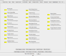
Another way of programming is by computer interface (such as LocoBuffer-USB or a PR4 for LocoNet) using JMRI DecoderPro. It provides a graphical interface, making configuration of the multitude of parameters easy.
This screengrab gives you an idea of the sound capabilities of the TSU-1000.
See the JMRI homepage here for more info on the Java Model Railroad Interface. The DecoderPro page has more info on what is needed to use it.
You can "test-drive" DecoderPro by simulating a connection to the layout (without requiring an interface) to get an idea of its abilities.
Videos
SoundTraxx Tsunami 2 Big Steam TSU-2200 DCC Sound Decoder Install - Athearn Big Boy - HO Scale
SoundTraxx Tsunami 2 Big Steam TSU-2200 DCC Sound Decoder Install - Athearn Challenger - HO Scale
Related FAQs
- No FAQs link to this page.


