DCC Tutorial (Basic System)
Summary: This tutorial will try to get your Digital Command Control Starter Set out of the box and get your trains running.
| Tutorial Topics |
|
| DCC Core Topics |
|
If you are just starting out and know nothing about Digital Command Control, please start at the Introduction to DCC article first.
While this article tries to make the content as basic as possible, Digital Command Control (DCC) is a bit more complex once you get into the nuts and bolts, however setting up a basic system takes just a few more steps than setting up a traditional analog power pack.
This article cannot cover every single situation, brand, or model, so we have to generalize when possible. The nuts and bolts of DCC do get rather technical: After all, you are dealing with a computer network! Fortunately, you do not need to understand computers to make DCC work for you!
Don't worry if you don't understand it right away, we'll present the same material several different ways in hopes that you'll understand one of them.
A Quick Comparison Between Analog and Digital Command Control
- Main article: DCC advantages over DC
An analog control system permits only one train per cab/block at any one time. A Digital Command Control system can be all one electrical block – many locomotives can be individually operated simultaneously! One person can run several locomotives at once, several people can each run one locomotive at a time, or several people can each run several locomotives at a time.
The key advantage of Digital Command Control over the traditional analog direct current systems is the elimination of separate blocks for train control. With DCC, many trains can be controlled independently within the same electrical block. Before DCC, control of speed and direction was related to the voltage and polarity present on the track, controlled by the operator using a potentiometer (or rheostat) and a direction switch. It is called analog[1] is that the speed and direction of the locomotive is directly related to the voltage and its polarity.
If you already have a layout wired with block control and want to switch to Digital Command Control, you can make the change. Please refer to the article on Converting to DCC for details.
What is Command Control?
Command Control is a method which allowed control of multiple trains without a lot of complex wiring. Many implementations have appeared over the years, but never gained widespread acceptance. Their proprietary nature and sometimes limited technology were the main hinderances they faced. Another term used was Carrier Control, which means the same.
What is Digital Command Control?
Digital Command Control is two things:
- A method using digital signals to control your locomotives, allowing control of several locomotives without complex wiring.
- Digital Command Control or DCC is a standardized method of signalling and control.
- The DCC Standards were developed by the NMRA to address the confusion which existed in the command control arena.
- Products bearing the NMRA DCC logo work to this standard, allowing products from different manufacturers to work together. Which protects your investment in DCC.
- The NMRA DCC Standards require the packaging of an NMRA DCC compatible product to identify features which are not present, [2] so you can make an informed decision prior to purchase.
Keep in mind that even with a standard for command control, there are command control systems on the market that, while digital in nature, are not NMRA DCC, and are not compatible with NMRA DCC Standards. They may have features that the typical DCC system lacks, but as they are proprietary, their support is limited to their manufacturer.
The focus of this Wiki is NMRA Digital Command Control.
Looking at the above pictures, do you still think Digital Command Control is complicated?
What exactly is Digital Command Control?
- Main article: How DCC works
Digital Command Control (DCC) is a scheme for controlling locomotives on a model railroad layout. It allows more than one locomotive to occupy the same electrical section of track. It allows for multiple operators to control multiple locomotives simultaneously, even in the same block (electrical division), which in analog (or DC power) is difficult at best, if not impossible.
If you only have the single DCC equipped locomotive that you bought along with your starter set, you can run a single non-DCC (analog) locomotive along with your DCC locomotives. If you want to know how this works, check out the section on zero stretching. Not all systems can do this, but many can.
DCC Components
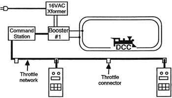
Let's give you the terms so you'll get familiar with them. The most basic Digital Command Control (DCC) system consists of several parts: a throttle, a command station, a booster, a decoder, and a power supply to run it all. Most systems also use a throttle network which allows multiple throttles to talk to the command station. Confused? Don't worry - it won't last!
Let's break this down a little.
- You use a throttle as an input to tell the system what you want a locomotive to do.
- The throttle sends your request over a throttle network to the Command Station.
- The command station creates a digital packet and forwards it to the booster.
- Some systems combine a command station and a booster into a single unit.
- The booster amplifies the digital data packet from the command station and sends it your railroad layout using your track wiring to the rails.
- A DCC-equipped Locomotive has a multifunction decoder inside. Every multifunction decoder is programmed with a unique address. The decoder listens to each digital packet as it goes past. It checks if the packet is valid (i.e. not corrupt), and if the address of the packet matches that of the decoder. If the decoder finds a valid data packet addressed to itself, the decoder performs the requested action. If the addresses don't match, or if the packet isn't valid, the decoder ignores the packet and continues whatever it was doing.
- Don't worry if the decoder ignores the first attempt. The command station continuously repeats all current data packets in case a decoder did not receive it. This is one way that DCC is reliable - error checking and multiple packet transmissions. We'll cover this in more detail later.
More Details
- The following sections are optional to understanding DCC. You are welcome to skip this section and go onto the DCC power section of this tutorial.
The following sections are summaries of devices. See the main articles for further details.
Throttle
- Main article: Throttle
The throttle is the box with the knob you turn or lever you move or the buttons you push to tell your engine what to do: speed up, slow down, stop, brake, turn the lights on/off, ring the bell, blow the whistle. There are various types of throttles- from a simple knob and a few buttons, to a NASA-style control panel that will scare you senseless!
Another term is "Cab". Because all the controls are in your hand (whistle/horn, throttle, brake, direction and sound effects), it is the equivalent of sitting in the cab. Cab and throttle are essentially the same thing.
Power Supply
- Main article: Power supply
The power supply is a device which supplies low-voltage AC or DC to the Command Station and Booster. Depending on the scale you are operating, you'll need a power supply with various voltages (covered later). For now, just think of the power supply as a device that converts the voltage supplied by the utility to a lower voltage required by the booster.
Command Station
- Main article: Command station
The command station is the real intelligence of the DCC system. Typically, the command station is combined with the booster into a single device; however you can buy additional booster-only units for larger layouts that need more power to run more trains. The command station contains a microcontroller (computer) and is responsible for all communication between the throttles and the decoders. The command station communicates with decoders by transmitting packets of data to them through the rails. Each digital packet tells a train how to run: fast, slow, forwards, backwards, or to turn lights, sound, and other effects on and off.
Booster
- Main article: Booster
The booster is sometimes referred to as a the "Power Station" and is responsible for combining the intelligence from the command station with the power of the power supply. Typically, a booster is combined with your first command station. More boosters can be added to the layout as demand for power increases.
Multifunction Decoder
- Main article: Decoder
While the Command Station is the intelligence of the layout, multifunction decoders are the brains of the locomotives. Each decoder is programmed with a unique address. The decoder monitors the DCC data on the rails and listens for commands with its address. All power in the locomotive flows from the rails, to the decoder, and then on to the motor, lights, and sound. These tiny special purpose electronic devices create the PWM signal for motor control, as well as creating any lighting or sound effects they may be capable of performing.
The decoders are programmable, allowing you to change the address, motor performance, and lighting and sound effects. The programming is stored in semi-permanent (non-volatile) memory that saves the information when there's no power to the decoder. They can be re-programmed with new information any time you like, and some functions can even be programmed while the train is running, see Decoder Programming for details.
Did you catch the fact that even the "unique address" can be changed? If you have a train with more than one engine, you can program them all to the same address and control them with a single throttle. If you accidentally program 2 engines with the same address, interesting accidents can occur.
Each decoder is different. There are certain standard functions that they are required to have, but most of the things that make brands and models of decoder different are optional - particularly when it comes to various light and sound effects and fine tuning motor control functions they offer. Check your decoder's capabilities before you buy them!
Some decoders are unique to a certain brand and model of locomotive: They are built in strange shapes to fit the odd nooks and crannies inside the locomotive. Check with various manufacturers to see if there's a special decoder for your engine.
Confused?
If not, skip this section as the article listed below may confuse you. Use the following article only if you still don't know what's going on.
If you are confused, please visit the Introduction to DCC article.
Videos
What's Next
Now that you have an understanding of the most basic DCC system, let's continue on to explain DCC power
This page can be quickly accessed at the following URL: https://2tra.in/tutorial Share this page
Also see the article on Starter Sets here.


