DCC Tutorial (Power)
Summary: The DCC signal contains both power and data. It consists of a series of pulses which represent the digital data. The pulses of data also power decoders. The data is represented by the time between the leading edges of the signal pulses. DCC does not have polarity, it has phase. Being digital, there is no concept other than High or Low.
| Tutorial Topics |
|
| DCC Core Topics |
|
Introduction to DCC Power
Power Concepts for Digital Command Control.
- Main article: DCC Power
- Main article: Videos:DCC Basics
Many references on the Internet insist Digital Command Control is AC (Alternating Current). DCC Multifunction Decoders are not compatible with AC power, such as command control systems offered by Marklin for their 3-rail AC trains.
Let's start off by saying: You do not need to fully understand the technical details of how DCC works. If you don't understand, don't worry. Come back in a few months and see if you understand it then.
Do you know the technical details behind high-definition satellite TV broadcasting? Does that keep you from enjoying your favourite show? Does it create a barrier to changing channels or turning your home theatre on?
All You Need to Know About DCC Power
- There is a binary signal on the power bus, which is sent from the booster to the train.
- There is full power on the rails at all times while the booster output is turned on. Voltage does not control loco speed.
- There is the signal phase present on the rails, where one rail is energized (ON) while the other is held to 0 or OFF. [1]
- The rails are identified as A and B, whose phase relationships can be handled by auto reversers when A meets B so you don't need to flip toggle switches.
- The phase of the rails does NOT control the direction of the locomotive.
- The signal is present at all times, in the form of the DCC packet shown below.
- DCC does not employ a DC voltage with the DCC signal riding on top, or any carrier signals. The rails have a series of pulses on them at all times.
- Power and the DCC commands are one in the same.
- Summary
- Simple On/Off binary signal, one rail always the inverse of the other.
DCC track power can be seen as:
- Power for motors/lights/sound/animation.
- A digital timing/control signal to tell decoders what to do.
Myths about the Digital Command Control
There are a number of erroneous myths circulating about Digital Command Control that refuse to fade away. Most are the result of applying analog concepts to a digital technology.
- DCC is Alternating Current[2]
- DCC is a form of Alternating Current
- DCC has Polarity.
Correct Answer: None of the Above. The DCC signal on the track is a binary signal, where it is either ON or OFF. One rail is always the inverse state of the other.
Digital Command Control Signal Details


Digital Command Control is a digital technology, which relies on the presence of a positive voltage, or no voltage. Being digital, it is either High or Low. There is no concept of negative voltages, as the Low state is defined as 0V. The DCC signal does not have polarity, it has a phase relationship.
Multifunction Decoders
Multifunction decoders are installed in vehicles. The multifunction decoder controls direction and speed, regardless of the vehicle's orientation or track voltage[9]. These decoders receive the DCC signal from the rails, read the data, then act on it. The DCC signal contains data in the form of the Address, Commands, and a Checksum byte. On the track, each pulse is repeated, once on Rail A, then on Rail B. The multifunction decoder samples one rail to extract the data.[10]
Phase
Analog control systems have Polarity; the Digital Command Control equivalent is Phase. Polarity is often incorrectly cited, introducing confusion by applying incorrect terminology to describe a situation.
- Main article: DCC Power/Phase Relationships
Turnouts and Phase Issue
There are two places where the phase is important: The frog and the switch rails. See the pages on turnouts for more details.
Reverse Loops
When the track loops back onto itself, Rail A will meet Rail B through the turnout's stock and point rails. For those applications, a method of inverting the phase of the loop is needed. This can be done automatically, or manually using a toggle switch. The multifunction decoder onboard the locomotive will continue as if nothing has happened.
Digital Command Control Signals

The digital waveform is created by your DCC system's (command station). It is sent to a booster (or multiple boosters for large layouts) where the DCC Commands are amplified to track power levels. The resulting higher voltage digital waveform from the booster is applied to the rails. The nominal transmission values are 58µS for a "1" and 100µS for a "0".
The multifunction decoder in the locomotive picks up the signal from the rails. The multifunction decoder has circuitry to process the DCC signal. The microcontroller the multifunction decoder is built around examines the data, and if it is addressed to it, acts on the instructions contained in the waveform. Additional circuits supply power to the motor(s), under control of the microcontroller which is responding to the information encoded in the waveform. Each decoder has an address, and will only respond to commands addressed to it.
Wireless DCC controllers have an RF transmitter in the handheld (throttle), and an RF receiver that controls the DCC controller (command station). But the DCC Signal and power still goes through the booster and the rails.
A Digital Command Control Packet
A DCC Packet is a defined group of signals. The technical term is a broadcast protocol. In the case of a broadcast protocol, the data is sent to all devices. Every packet consists of a minimum of 38 bits.
The packet always begins with a preamble of at least twelve bits representing a value of one are transmitted. No other DCC command can consist of twelve sequential bits set to equal 1. The preamble is considered to be floating, and provides sync information to the devices, making the entire system self-synchronising without additional clock signals.
When a decoder sees the preamble, it immediately takes note. After the preamble the data bytes begin. The first segment is the address byte, the next is the instruction byte. The NMRA DCC standard only defines a few basic instructions. The final segment is the error correction byte. A typical packet consists of three or four data bytes, or 24 to 32 bits. The final segment is the packet end bit, equal to 1. Each byte is separated with a zero bit.
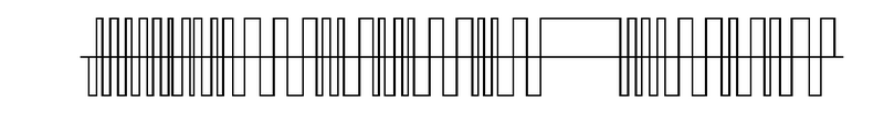
A DCC packet. This one also illustrates Zero Stretching (Analog) operation.

The command station will either transmit idle packets, or retransmit previous packets. No data, no track voltage. The command station will have logic in it that will determine the sequence and repetition of packets to ensure that the bandwidth available is used efficiently.
Conversion from Analog/Direct Current to Digital Command Control
Conversion of a layout from Analog direct current (DC) operation to Digital Command Control usually means rewiring. The reason is a fundamental difference between wiring methodology: Direct current layouts rely on multiple low current power supplies located around the layout, with each powering a single block/train at a time. Since one power supply is routed to a block in the immediate vicinity, they do not require heavy wire to carry large currents, as they do not supply power to multiple trains a great distance from the power source.
DCC gives you the ability to run multiple trains simultaneously from one booster, and most modellers soon begin doing that because is it easy and possible. Which means more current draw, requiring wiring that can handle that.
- For more comparisons, read the DCC Advantages Over DC page.
- See the track wiring page for more details.
What Is Next?
Continue to Getting started with a Starter Set.
- ↑ This would be considered a bi-stable signal
- ↑ Alternating current is the current that flows in a circuit stimulated by an alternating voltage. DCC signals are not continuously changing in amplitude and polarity.
- ↑ Analog: Relating to or using signals or information represented by a continuously variable physical quantity such as spatial position, voltage, etc.
- ↑ The time between the leading edge of the pulses represents the data value.
- ↑ The time between the leading edges of the pulses determines the value.
- ↑ Floating refers to the signal having no reference to earth ground. A battery is a floating power source.
- ↑ The scope's probe is clipped to one rail and its ground connected to the other. The result is that the reference point for zero can be either Low or High depending on the state of the rail at that time.
- ↑ Marklin three rail keeps the outer rails at ground potential, and applies their command control signal to the center rail using an H-Bridge circuit like a DCC Booster. The result is a pseudo Alternating Current signal for their command control system, and is less costly than their older method of generating the center rail's signals. The Marklin three rail system is not floating, unlike DCC, where the track is floating.
- ↑ The NMRA defines the positive rail as the right hand rail as seen from the engineer's seat in the cab.
- ↑ This works regardless of the orientation of the locomotive. If one rail carried pulses of a negative amplitude, the decoder would only see 0V, and would not be able to extract any data if the decoder was sampling that rail.