Configuration Variable/Configuration Register CV29
Summary: Configuration Register 29, also known as Mode Control, enables or disables a number of multifunction or accessory decoder features using bitswitches.
Configuration Register 29
- Referred to as CV 29 Share this page
CV29 controls a number of features on both Accessory and Multifunction Decoders. It does so with Bit Switches to activate features by setting a specified bit on or off.
For the purposes of this article, the term Enable means the bit has been set to a value of 1, or ON. To Disable a feature, the bit is set to 0 (zero, OFF).
Setting the Configuration Register
- This is a more advanced subject, and is for information only. Other bits may need to be set manually.
Your DCC system may automatically set some bits, such as enabling the Extended Address Mode, when programming a multifunction decoder. Other bits may need to be set manually. For example, subtracting 4 from the default value will set the multifunction decoder for NMRA DCC operation only.
As CV29 has a large impact on multifunction decoder operation, it is not advisable to blindly write values to it. Many will tell you to "Write this value to CV29 and all will be well!" If you wish to alter this CV, first read the value in it, determine the changes needed, calculate the required value, then write that value. Making changes without regard for the current state of CV29 may lead to more problems than solutions.
Hint: Software such as JMRI can set CV29 to the correct values without any user calculations.
Multifunction Decoder
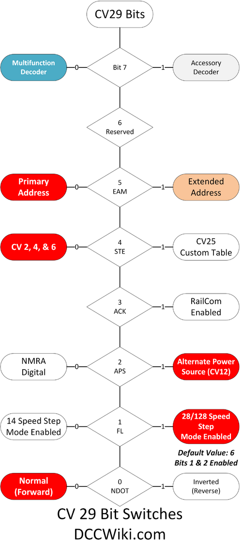
The Modes in Red are the Defaults for a Multifunction Decoder's CV29.
Bit 7
This bit determines if the decoder is an Accessory Decoder when enabled, or a Multifunction Decoder when equal to 0.
Bit 6
Bit 6 is not used, as such it cannot contain any value. It is reserved for future applications.
Extended Address Mode (Bit 5)
When enabled the Extended Address Mode is available.[1]
Speed Table Enable (Bit 4)
Enables the speed table in CV25, otherwise a three point speed curve (CVs 2, 5 and 6) is used.[2]
Acknowledge (Bit 3)
This bit enables Bidirectional Communications, such as RailCom. Normally, this bit would not be used.[3] If the decoder lacks this capability the bit would default to OFF and cannot be changed.
Alternate Power Source (Bit 2)
When disabled, the multifunction decoder will only respond to a DCC signal. Few decoders support any modes other than analog or NMRA Digital (DCC).[4][5] Many modellers disable the Alternate Power Source (Analog Direct Current) to prevent a runaway locomotive.[6]
If the Primary Address is set to 0 (zero) the multifunction decoder will respond to the mode selected in CV12. In most instances the result is a runaway locomotive.
FL Location (Bit 1)
This bit controls the location of the Forward Headlight instruction within the DCC Packet. If Bit 1 has a value of 0 (zero), bit 4 of the speed instruction controls the state of FL. This provides 14 discrete speed steps[7]. If Bit 1 is set to a value of 1 (its default value), the multifunction decoder will operate in 28/128 speed step mode. Read the Speed Steps article for more information.[8]
If a multifunction decoder is configured for 14 speed steps, and operated using 28/128 speed steps, the headlight will toggle on or off with each throttle increment or decrement.
The Fourteen Speed Step mode is obsolete, and may not be available. Multifunction decoders now default to 28/128 mode. See Mode Change in the Speed Steps article.
Normal Direction of Travel (Bit 0)
The Normal Direction of Travel establishes the forward direction of the locomotive. It also changes the behavior of FL. Use with caution. If the value in CV29 is an even value, NDOT has not be enabled. If odd, NDOT is enabled. To reverse the direction of the locomotive using NDOT, you just add or subtract 1, depending on the CV's value being Even or Odd. [9][10]
Accessory Decoders
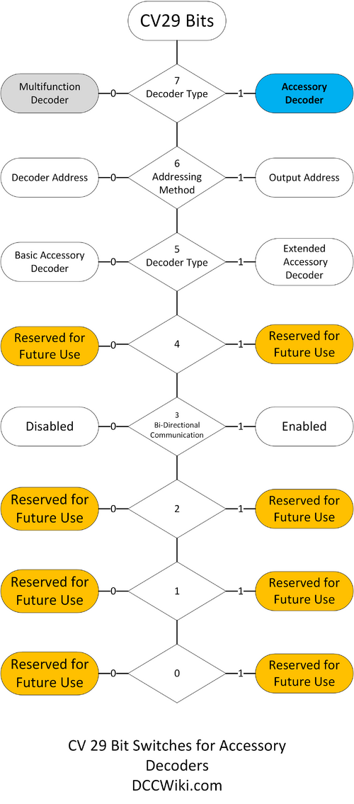
Accessory decoders also use CV 29 for configuration purposes. As always, if the decoder does not support a feature contained in this table, it must not allow the corresponding bit to be set improperly (i.e. the bit should always contain its default value).
See Accessory Decoder Addressing for details on addressing modes.
To identify itself as an Accessory Decoder, Bit 7 of CV29 is set to a value of 1, whereas a Multifunction Decoder has a value of 0 (zero)
Bit 6, Addressing Method
Addresses are available from 1 to 2044. Each address location can control a pair of functions, usually either two solenoids for turnouts or two LEDs for signals.
Different manufacturers view this range in one of two ways:
- ) 511 decoder addresses, each with 4 sub-addresses, or
- ) 2044 individual output addresses
Not all command stations support all of the possible addresses in that range.
Accessory decoders are addressed differently than multifunction decoders. Each address defines an individual cell, changing that cell causes turnout motors or signal aspects be activated.
Bit 5, Accessory Decoder Type
This bit determines whether Basic or Extended addressing will be used. The Base Address is 9 bits, which allows four outputs at this address.
Extended Address uses 11 bits, which correspond to a specified output. Often used for signalling purposes.
Not all command stations support all the possible addresses available.
Communications
This allows two way communications on a throttle network. It may be necessary to change this feature in some applications.
All accessory decoders must have the capability to receive DCC commands via the track bus to be considered compliant to the DCC standard.
Bit Switches
| Bit Position | Bit 7 | Bit 6 | Bit 5 | Bit 4 | Bit 3 | Bit 2 | Bit 1 | Bit 0 |
|---|---|---|---|---|---|---|---|---|
| Value | 27 | 26 | 25 | 24 | 23 | 22 | 21 | 20 |
| Decimal Value | 128 | 64 | 32 | 16 | 8 | 4 | 2 | 1 |
| Hexidecimal Value | $80 | $40 | $20 | $10 | $8 | $4 | $2 | $1 |
| Default Binary Value | 0 | 0 | 0 | 0 | 0 | 1 | 1 | 0 |
| Result (Decimal) | 0 | 0 | 0 | 0 | 0 | 4 | 2 | 0 |
| Sum | 6 | |||||||
Example: Extended Address Mode Enabled (Multifunction Decoder)
| Bit Position | Bit 7 | Bit 6 | Bit 5 | Bit 4 | Bit 3 | Bit 2 | Bit 1 | Bit 0 |
|---|---|---|---|---|---|---|---|---|
| Value | 27 | 26 | 25 | 24 | 23 | 22 | 21 | 20 |
| Decimal Value | 128 | 64 | 32 | 16 | 8 | 4 | 2 | 1 |
| Selected | ||||||||
| Binary Value | 0 | 0 | 1 | 0 | 0 | 1 | 1 | 0 |
| Result (Decimal) | 0 | 0 | 32 | 0 | 0 | 4 | 2 | 0 |
| Sum | 38 | |||||||
| Sum, Hex | $26 | |||||||
The Multifunction Decoder's default value for CV29 is 6 (Bits 1 and 2 are set to One/On) in both decimal and hexadecimal numbers. As shown in the examples, adding a value of $20 (32 in decimal) to the default value in CV29 by enabling bit 5 allows extended addresses. Subtracting $20 from the value in CV29 by deselecting bit 5 turns it Off. In many cases this step is unnecessary as the command station's software will set bit 5 for a Primary or Extended address.
Further Reading
NMRA/NMRA_Standards
- Main article: NMRA/NMRA_Standards
Specifically, S-9.2.1 and S-9.2.2
External Sites
- CV29 Calculator
- CV29 Explained at the NCE ZenDesk.
Videos Regarding Programming
References
- ↑ To Enable Extended addresses, Bit 5 is set to "1". When this bit is cleared (set to zero), the decoder reverts to the primary address in CV 1.
- ↑ Not all multifunction decoder support CVs 2, 5 & 6.
- ↑ Some online calculators for CV29 may not allow this bit to be set.
- ↑ This bit is often used to disable DC/Analog operation, preventing runaways.
- ↑ With APS enabled, CV 12 determines the modes available.
- ↑ A distorted DCC signal, usually a result of poor wiring practices, will cause the decoder to switch to the alternate power source if enabled, causing a runaway.
- ↑ Fourteen Speed step mode is now obsolete, new multifunction decoders default to 28 speed step mode.
- ↑ A speed and direction instruction is used send information to motors connected to Multifunction Digital Decoders. Instruction "010" indicates a Speed and Direction Instruction for reverse operation and instruction "011" indicates a Speed and Direction Instruction for forward operation. In these instructions the data is used to control speed with bits 0-3 being defined exactly as in S-9.2 Section B. If Bit 1 of CV 29 has a value of one (1), then bit 4 is used as an intermediate speed step, as defined in S-9.2, Section B. If Bit 1 of CV 29 has a value of zero (0), then bit 4 shall be used to control FL3. In this mode, Speed U0000 is stop, speed U0001 is emergency stop, speed U0010 is the first speed step and speed U1111 is full speed. This provides 14 discrete speed steps in each direction.
- ↑ Using the NDOT to rectify an incorrectly wired motor is considered bad practice. NDOT is often used with consisting.
- ↑ When the DIR bit is enabled Locomotive and headlight (FL, Forward Lamp) will run in the opposite direction, useful for long hood forward operation. This bit is the NDOT (Normal Direction of Travel).

