Turnout
Summary: Many turnouts are compatible with DCC right out of their packaging. Making older turnouts compatible with your Digital Command Control system isn't hard. Here are ways to improve and modify commercial turnouts.

Turnouts
With the advent of two rail track, the challenge facing commercial turnout manufacturers was the differing rail polarities at the heel of the frog. The painless solution was an electrically insulated frog. A number of available manufactures used either metal frogs with gaps to isolate them, or a simple cast plastic frog.
A more complex method was the live frog, where its polarity was controlled by the route chosen. While this method worked, it created short circuits in certain track configurations, mandating the installation of insulated rail joiners.
Where Digital Command Control simplified track wiring and eliminated the concern of polarity, a new problem arose. With the entire track powered all the time, there is the complication of a phase mismatch at the frog resulting in short circuits. Improved design resulted in manufactures featuring isolated switch rails which are in phase with their stock rails, yet cannot eliminate phase mismatches at the frog or point rails. Certain practices are necessary to prevent phase mismatches. With a little modification and careful installation, any turnout can be used with DCC.
The Basics of Turnouts and Digital Command Control
- All turnouts work with Digital Command Control
- There are no turnouts that do not work with Digital Command Control
- If a turnout works with analog it will work with Digital Command Control
Terminology
Many modellers use turnout and switch interchangeably.
In prototype practice:
- A SWITCH consists of two switch rails with all the necessary accessories.
- A SWITCH is not a TURNOUT, only part of it. Branching from one track to another requires a turnout with both a frog and a switch.
- The terminology is from the US Steel Trackwork Catalog. Some images/videos used in this article may not conform to standard prototype nomenclature.
A complete turnout consists of:
- The Switch
- A straight stock rail
- A straight closure rail
- Two switch rails
- A curved stock rail
- A curved closure rail
- The closure rails form the wing rails of the frog
- The Frog
- The frog is formed by the wing and point rails
- The frog has a toe, formed by the wing rails and a heel formed by the point rails
- The point rails lead out of the heel of the frog
Unfortunately, many sources have creative but flawed terminology. Incorrect terms make troubleshooting or explaining an issue problematic. The common culprit is confusing the point and switch rails. The terms used on the DCCWiki are those found in the USS Track Work catalog. Unfortunately, some of the drawings presented may not align with the accepted DCCWiki terminology.

Detailed Diagram of a Turnout

Frog Components

As shown in the drawing, the frog consists of several parts.
- The primary components of the frog are the LH and RH Wing rails, which constitute the TOE of the frog.
- The HEEL of the frog is created by the Point rails. The HEEL has the flangeways between the Point and Wing rails.
- The THROAT is the section where the Wing rails diverge before the juncture of the Point rails. In prototype and model practice, it is often formed from a single cast part.
As the wheel proceeds along the closure rail into the toe of the frog, the wing rail supports the wheel as its tread transfers from the wing to point rail. At no time is the wheel unsupported. The wheel continues along the point rail as it exits the heel the frog. Close clearances allow this. The guard rails (not shown) are there to keep the truck moving in the correct direction, if necessary. The profiles of the wheel and rail keeps everything centered on the rails, while the flanges are there for additional guidance when needed.
In modern prototype practice, the frog is often a cast metal part. It is work hardened by the passage of a train, or by using explosives prior to installation.
Commercial model turnouts feature a number of methods to construct the frog, including cast metal or plastic, or forming them using rails and moulded plastic. When hand laying your turnouts, the frog will be formed using rail stock, or a commercial casting. The advantage of hand laid track work is the clearances can be close to the NMRA standards. Using your NMRA gauge on a commercial product will reveal a number of compromises were made.
Frog Numbers
| Turnouts | DCCWiki.com | ||||
|---|---|---|---|---|---|
| Frog number | Radius, Feet | Degree of Curve (DMS) | Inches | ||
| O Scale | HO Scale | N Scale | |||
| 5 | 177.8 | 32-39-56 | 44 | 24 | 13 |
| 6 | 258.57 | 22-17-58 | 65 | 35 | 19 |
| 8 | 487.28 | 11-46-44 | 122 | 67 | 37 |
| 10 | 779.39 | 7-21-24 | 195 | 107 | 58 |
| 12 | 1104.63 | 5-11-20 | 276 | 151 | 83 |
| 16 | 2007.12 | 2-51-18 | 502 | 275 | 151 |
| 18 | 2578.79 | 2-13-20 | 645 | 354 | 193 |
| 20 | 3289.29 | 1-44-32 | 822 | 451 | 247 |
The number of a frog is the ratio of the spread to its distance from the theoretical point (where the long and short point rails would form a point, not the actual juncture).
A number 4 frog is 1" in 4". The spread is measured at right angles to the center line. The actual angle formed is 14 degrees 15 minutes.
As per prototype practice, for high-speed movements a turnout of #16 to 20 is recommended. Mainline slow speed movements, #10 to 12. Yards and sidings, #8. For modelling purposes, #8 is good for most applications, with smaller frog angles for yards and branch lines.
As the table shows, a number 20 turnout requires a radius of 21 feet (247/12") in N Scale. For modelling purposes, a number 10 or 12 turnout is reasonable compromise at five to seven feet (in N). In H0 Scale a #10 has a radius of 9 feet.
Digital Command Control and Turnouts
Digital Command Control has certain requirements that must be met by your track work. Two related electrical issues are the switch rails (sometimes incorrectly called the points) and the frog. Using your NMRA gauge to verify the clearances of the turnout as goes a long way. Out of gauge wheel sets can cause shorts and derailments. Consider replacing plastic wheels with metal ones, as plastic wheels can wobble due to manufacturing issues. Verify that the trucks have free movement in both horizontal and vertical planes.
- Short Circuits are disruptive and should be minimized. Since full power is available on the rails at all times, a short will cause interruptions in your enjoyment. They can also allow enough current to flow to weld things together, which is never a good thing. Your boosters will react quickly and shut down everything, and if the short is not cleared, will begin cycling on and off until it is cleared.
- Wheels on Rails is not the most reliable power delivery system. Your locomotives need a clean, uninterrupted Digital Command Control signal on the track for proper operation. Electrically unreliable turnouts will cause problems like stalling, or in the case of sound decoders, restarting of the prime mover.
- A careless operator can foul a turnout, creating a short, causing the Digital Command Control signal to be cut off. Or it may just cause problems until the points are aligned correctly, inconveniencing everyone else until power is restored.
- You want to run your trains and have fun, and troublesome turnouts are not going to improve the experience.
Older turnouts may present issues with Digital Command Control. When they were made Digital Command Control wasn't available or not widespread. Later versions may have been improved to deal with issues arising with Digital Command Control.
Frog Types
Two distinct frog types found in Model Railroading: Live (powered) and Dead (unpowered).
Dead (Insulated) Frogs
A dead frog is isolated from the rest of the track, physically and electrically. Typically, the frog will be made from an insulating material such as plastic, but a metal casting can be used as well. Others used rails with gaps to construct the frog, this method made turnouts which were much more compatible with Digital Command Control than older turnouts with live frogs, at less cost. The PECO Insulfrog is an example, as are Atlas Snap Track and almost all turnouts made with brass rail. Also available are turnouts by Micro Engineering, Walthers, the Atlas Custom Line Code 83 turnouts and others with metal frogs insulated from the adjoining rails.
- Atlas
- Peco Insulfrog
- Peco's insulated frog turnouts are ready to use out-of-the-box with the slight caveat described below (see Small Frogs).
- Micro Engineering
- Walthers/Shinohara Digital Command Control Compatible (Older ones may need come work to make them compatible)
- Hand laid turnouts, such as those made using Fast Tracks jigs or Central Valley kits
Dead/Insulated frog turnouts are shown in the picture for Self Isolating Turnouts.
Live Frogs
Live Frogs are metal and electrically connected to the track power. They have the advantage of less unpowered track but are more complicated to wire up. They require insulated rail joiners or gaps on the point rails to prevent a short. Some designs may incorporate a gap at the heel of the frog to prevent a short.
Isolated frogs are made from metal but are electrically isolated from all the other rails which makes them behave very much like insulated frogs. However, being metal, this gives you the option to convert them to live frog operation by attaching a feed wire to the frog.
There are two ways that live frogs can get their power:
- Self Powered
- Frog Switching
- Just because the frog is constructed from metal (a casting or with rails) does not mean it is live.
An example of a live frog is the Peco Electrofrog.
Isolated frog turnouts are shown in the picture Non-Power Routing Turnouts.
Turnout Overview
- Also see the page on DCC Friendly Turnouts.
Full-size turnouts or models, the terminology is pretty much the same.

Types of Turnouts Used in Model Railroading
- Non-Power Routing
- Self Isolating or Power Routing
- Non-isolating Power Routing
- Self Powered
Commercial turnouts are produced in many different shapes, sizes, sleeper types, rail profiles, and degrees of realism. To complicate the choice there are various different electrical behaviours and some are labelled "DCC-Ready" or "DCC-Friendly" and others are not. So, which type should you choose?
You do not have to buy turnouts labelled "DCC-ready" and you do not have to modify existing turnouts when converting a layout to Digital Command Control. You should choose the turnouts that best suit your overall requirements and don't go out of your way to find "DCC-ready" or "DCC Friendly Turnouts". However, there are several special considerations to bear in mind and if you're just starting out on a Digital Command Control project it will be well worth investing the time to understand the different types of turnouts, their various benefits and the best way to wire them up.
But before you read on and get too confused, remember a few rules...
- All turnouts work with Digital Command Control
- There are no turnouts that don't work with Digital Command Control
- If a turnout works with analog it will work with Digital Command Control
Power and Non-Power Routing Turnouts

This is the issue which confuses many modellers.
With analog power, using the turnout as an electrical switch has advantages. A locomotive can be driven onto a siding, and then the turnout is aligned against it. The turnout provides two functions: It controls the routing of electricity in addition to the route the train takes. The turnout could disconnect power to the siding, or just make both rails the same polarity resulting in no voltage between the rails. This eliminated the need for additional wiring and switches to control power to the siding.
With the advent of Digital Command Control, track wiring changed. The ability to turn off power to siding was no longer an advantage or even needed. Multiple blocks were eliminated, as the entire layout now had a single source of power. Issues arose with turnout wiring, as a power routing turnout could cause a short if the point rails were connected together, as the turnout controlled the phase of the point rails. This leads to short circuits when the switch rails connected the incorrect phase to the point rails.
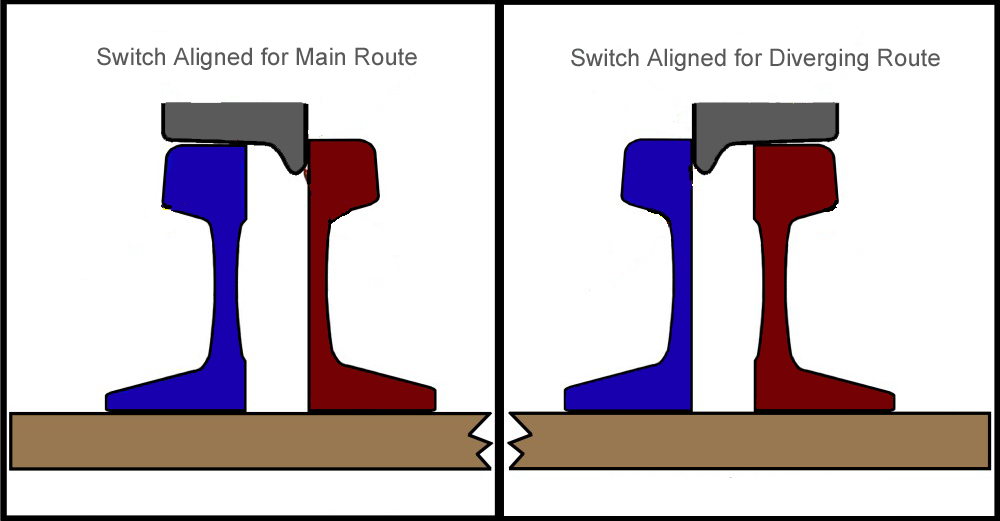
Non-Power Routing Turnouts
In Non-Power Routing turnouts all routes are powered. In commercial turnouts, this is achieved with internal bonding wires (usually on the underside) between the stock and switch rails or the stock and closure rails (the diagram shows the latter case but they are effectively equivalent to each other). Since the stock and switch rail pair are electrically connected and share the same phase relationship, there should be no shorts caused by a wheel bridging the gap between them. Their point rails are usually electrically connected to the appropriate rail.
Atlas and Roco are examples of non-power routing turnouts.
Power Routing Turnouts
Self-Isolating
Self-Isolating Power Routing Turnout. Note the frog is dead electrically.
Insulfrog showing Power Routing


Self-Isolating / Power Routing turnouts are those which only power the track on the selected route, the other route is electrically dead. This was a good feature for analog layouts because it automatically isolates a locomotive sitting idle on a siding. The point of using Digital Command Control is that it's not necessary to cut the power to make a locomotive stop, and doing so will prevent things from working; such as sound, lights, and CV programming. The solution is simple though, just add power feeds to the track in the siding. Insulated Rail Joiners or gaps cut into the track are needed to avoid creating a short.
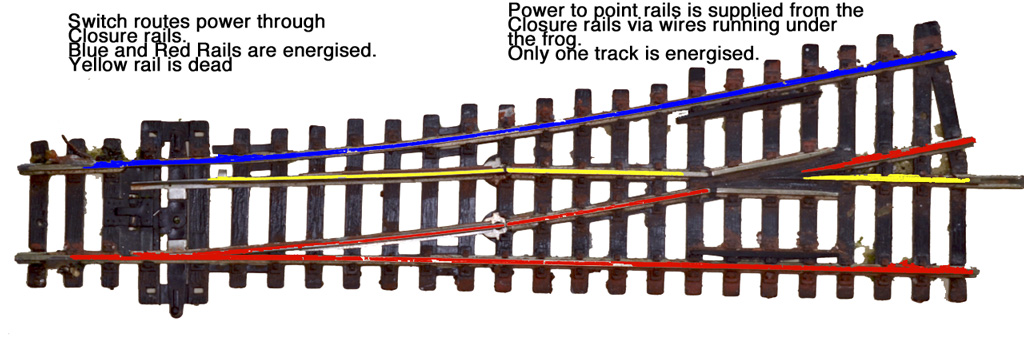
This feature is usually implemented by wires connecting the closure rail to the appropriate point rail, located beneath the frog. The switch rails function as a electrical switch, connecting or disconnecting power.
Peco Insulfrog and Hornby are examples of self-isolating power routing turnouts.
Non-Isolating

Non-Isolating Power Routing turnouts power the track only on the selected route, the other route has the same phase on both rails. To a locomotive, it sees no potential difference (voltage) between the two rails. Like the self-isolating turnouts this is not good for Digital Command Control, as it causes a short circuit. And whether you're using Digital Command Control or not, this type of turnout needs isolating rail joiners or gaps (not shown in the diagram) on the end of the point rails to prevent short circuits when power is fed independent of the turnout to the downstream track.
These turnouts have their point rails, closure and switch rails electrically connected together. In some cases, this is partly because the closure and switch rails share the same metal hinge mechanism. The frog may or may not be live, in the diagram below a live frog version is shown. Shorts may occur if a metal wheel's tread bridges the gap between the switch and stock rail.
PECO Electrofrogs are examples of non-isolating power routing turnouts.
Shinohara Turnouts (Walthers) come in two varieties. The older ones are non-isolating power routing. They can be identified by the metal bars joining the switch rails together and there are no gaps at the toe and heel of the frog. Small metal tabs under the points connect the switch rails to either stock rail.
Self Powered
With the self-powered or Power Routing turnout, the frog is electrically connected to switch rails and therefore takes its phase according to the route selected by way of the switch rail contacting the stock rail.
The main task is gapping the point rails. With ready-made turnouts this simply means installing insulating rail joiners on those two rails. The second task you may want to perform is wiring a frog feed that also provides the correct phase to the frog. This avoids having to rely on the contact between switch and stock rails making a good electrical connection. This can be controlled using either a SPDT toggle switch or by contacts on a turnout motor.
Peco call theirs Electrofrogs. Peco's live frog turnouts are ready to use out-of-the-box (using insulating rail joiners on the point rails) as the self-powered type. However, they are designed to be easily converted to the other type (frog switching) if desired. Without modification, the risk of shorts between the switch rail and its adjacent stock rail exists, as both switch rails share the same phase.
- Note: PECO is discontinuing the Electrofrog, replacing it and the Insulfrog with the Unifrog.
Many brands offer these types of turnouts such as Micro Engineering's older turnouts, Shinohara, Walthers and PECO's Electrofrog.
Frog Switching

With frog switching, the frog is isolated from all the other rails and must get its power from a separate power feed that switches accordingly.
The next diagram shows "Digital Command Control-Friendly" turnouts with the frog phase switch added. Here a switch is mechanically linked to the tie-bar so that whatever operates the points also operates the frog switch. This can either be a turnout motor with a built-in switch, or a SPDT switch mounted at the side of the layout with a rod or wire-in-tube linking it to the tie-bar. An alternative to a mechanical switch is an electronic device such as the Frog Juicer.
Short Circuits
Three types of short circuits can occur at turnouts. Most of the time none of these should be an issue but if you want to improve the reliability of your layout take note. None of these issues are specific to Digital Command Control but since a short on a Digital Command Control layout trips the booster and cuts power to all of the locomotives in the same district, the effect is much more annoying.
Small Frogs
The smaller an insulated frog's length, the less dead track there is to inadvertently stall your locomotive. However if they are too small and your rolling stock wheels are too wide there is a risk that a metal wheel lacking a 3º taper will bridge the gap between the two point rails where they meet at the heel of the frog.
A common cause of shorts at the heel of the frog is with wheels which, while meeting NMRA Standard S-4.2 for scale wheels, lack the recommended 3˚ taper shown in RP-25. This is also an issue with larger frog numbers, as the point rails will have less of a diverging angle.
During installation the point rails must have insulating rail joiners to isolate them from the downstream trackwork. This allows the turnout to control power flow to the point rails, and eliminates the issue with bridging the point rails in the frog. This is important if the point rails are electrically bonded together.
If this proves to be a problem for you, see the page on the Peco Insulfrog for a simple fix.
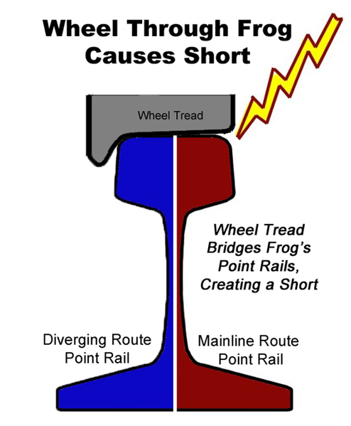
Wheel tread bridges the point rails at the heel of the frog, causing a short. Wheels with a 3˚ taper will not have this issue.
Peco Insulfrog Frog Short. The wheel is bridging both point rails on the heel of the frog


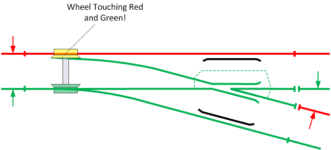
Stock Rail to Switch Rail Shorts
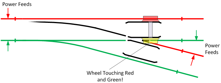
This is another issue that can occur with crude profile metal wheels, or with wheel sets or rails out of gauge. If the wheel's tread is wide enough the back of the wheel's flange can touch the side of the open switch rail.
Out of gauge wheel sets or trackwork where the wheel can bridge the gap. Verifying wheel gauge and turnouts clearances with an NMRA Gauge can identify these issues. In the case of wheelsets, they should be checked and corrected as necessary before new rolling stock goes on your layout.
Out of gauge rails or wheel sets can allow a short to occur between the stock and switch rails. Crude profile wheels, with wide treads and thick flanges can also cause this problem.
Peco Electrofrog: Short caused by a metal wheel bridging gap between the switch rail (green) and stock rail (red).


If you hand lay your trackwork, use an appropriate gauge to check the clearances during turnout construction, especially the switch rail clearances. The gauge can also identify issues with commercial turnouts as well, since compromises are made for manufacturing.
Insulated frog or live frog turnouts can have this issue depending on how the switch rails are wired. Ideally, they should be isolated from the frog and electrically connected to the adjacent stock rail.
This issue can occur with Peco Electrofrogs because out-of-the box both switch rails are electrically connected to the live frog which means the one rail will have the opposite phase of the adjacent stock rail. Peco supply instructions with all their Electrofrog turnouts for modifying them to solve this problem.
Running into a Mis-aligned Turnout
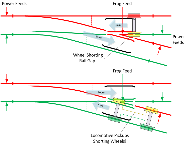
Any type of setup (Digital Command Control-Friendly or not) with a live frog has the hazard of a potential short circuit when you run into a turnout set against you. By definition, the live frog is set to the correct phase for the correct route and therefore the wrong phase for the wrong route. If a metal wheel bridges the gap at the frog, or the locomotive's front and back pickups span the gap then there will be a short. If you don't want this to trip your booster or circuit breaker you can either use a Frog Juicer to automatically correct the phase, or a Frog Current Limiter to reduce the current that can flow through the shorted frog.

Remote Operation
- Main article: Turnout Operation
On a Digital Command Control layout, turnouts can be operated remotely by Turnout Motors controlled by Accessory Decoders using commands sent from a Throttle.
See Also
- Wiring Turnouts
- Turnout Operation
- DCC Friendly Turnout
- Turnout Motors
- PECO Electrofrog
- PECO Insulfrog
- PECO Unifrog
- Shinohara turnouts
- Walthers turnouts
- Video:Atlas Custom Line Turnout Features
- Micro Engineering
- Wiring Crossings
References
- USS Track Work Catalog
- Modifying Peco Electrofrog Turnouts (This resource may no longer be available).
- Engineering Analysis and Geometric Design of Model Railroad Turnouts NMRA Technical Note TN-12
- Trackwork Handbook by Paul Mallery
- FROGS AND SWITCHES at the Catskill Archives
- Wiring Point-work & Special Track Conditions for DC or DCC, DCC Concepts Ltd.