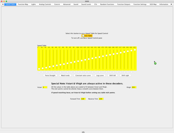
Speed Table
Summary: A Speed Table is a series of settings to customize how fast or slow a locomotive should run at a given throttle setting.
|
See the Video. |
Many multifunction decoders have a built-in curve (Speed Table) that is a standard setting of how fast or slow the vehicle should run at a given throttle speed. The speed curve between manufacturers can differ. Also, you will need to take into account different models and brands of locomotives. However, there are a few ways to alter that speed curve. Some decoder brands even allow you to program many different speed curves into the decoder, and allow you to select which one to use on the fly.
To handle the task for limiting speed, we use a speed table to set the maximum speed. That is, you specify how fast (or slow) each speed step will be - hence a curve.
Even on identical models some tuning may be required, as slight differences between motors and gear sets will exist.
Speed curves are only available on multifunction decoders with 28 and 128 speed steps. Not all decoders include CVs 2, 5 and 6 required for trimming speeds either.
Why Change it?
Your throttle only has a limited number of 'notches', or speed steps. You can have 14, 28, or 128 different speed steps. At the lowest ones, the loco will probably not move at all. At the highest ones, your loco may move too quickly. The speed table allows you to adjust the 'notches' to include only the realistic range of speeds, allowing for finer control.
It also allows you to define how the locomotive will accelerate, and at what rate.
Types of Speed Tables
There are two ways to implement a speed table.
- Three Point Speed Table
- The simplest is to set the starting speed, the midpoint speed, and the fastest speed the locomotive can go, using VStart, VMid, and VHigh.
- User Loadable Speed Table
- The second method is to specify 28 points along the speed curve – over nine times as complex than the V-Start method – but if one can't get a consist properly speed matched, one may be forced to go this route.
In most cases, the default or built-in speed curve work just fine. With multifunction decoder features such as VStart, VMid, and VHigh. , it's possible to match speeds of dissimilar locomotives. But, if one cannot attain the speed curve desired by modifying the built-in speed curve(s), one can always make use of the user-loadable speed table to configure the exact curve needed.
Three Point Speed Table
V-Start, V-Mid, V-Max
These CVs are not mandatory as defined by the NMRA DCC Standard S-9.2.2.
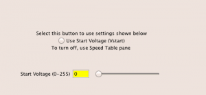
These would be the equivalent of off-idle, part throttle, and wide-open throttle. These CVs set the minimum starting voltage, the mid-range voltage, and the maximum voltage which will be applied to the motor. These tailor the throttle's response. [3]
- CV2: VSTART, works with CV65 Kick Start or the dithering or torque compensation, for smooth starts [4]
- CV5: VHIGH, Optional, controls the maximum power that will be applied to the motor [5][6]
- CV6: VMID, Optional, adjusts the power available in the mid-range. [7][8]
Additional Recommended[1] CVs
- CV3: Acceleration Rate: Determines rate of acceleration, useful values are 5 to 10 [9]
- CV4: Deceleration Rate: Same, but works to slow the locomotive [9]
If the momentum values are set the formula used by the decoder is (CV value)0.896/Speed Steps
To set a linear speed curve, the value of CV6 is the average of CV2 and CV5:
CV6 = (CV2 + CV5) ÷ 2
For example, if CV2 = 14 and CV5 = 181, CV6 = (14 + 181) = 195, divide by two and the result is 97.5. CV6 could be 97 or 98, depending on if it is rounded up or down, because CVs can only contain an integer value.
User-Loadable Speed Table
The user-loadable table provides 28 CVs (67-94) for the speed table, plus three others (65, 66, and 95) for fine-tuning. CV67 is for speed step 1 in the 28 speed-step mode. CV68 is for speed step #2, CV69 is for speed step 3, and so on all the way up to CV94 for speed step #28.
For fine tuning, you can use CVs 66 and 95 for forward and reverse trims. CV65 is for Kick Start, to help the loco get started on speed step 1, to overcome stiction.
With some multifunction decoders, the user-loadable speed table is only available in the 14 or 28 speed-step modes. Advanced decoders can expand the speed table for use with the 128-speed-step. It does this by stretching the 28 CVs, or interpolating, into 128 virtual CVs and computing the in-between points.
Using the user-loadable speed table is optional. The default setting will typical function good enough to get started and allow running trains.
Equipment Requirements for User-Loadable Speed Table
The user-loadable speed table is provided solely by the decoder. It requires a DCC system capable of programming CVs 67-94. To use the user-loadable speed table, set bit 4 of CV29 and to return to the built-in speed curve, unset it.
Due to the complexity of programming user-loadable speed tables, we highly recommend using DCC software to assist in this task. Some software applications allow the use of a graph or some other graphical tool to represent the speed for each step. Software programs will also help you to reconfigure or fine tune the speed table. Also, some software applications allow you to save and restore speed tables so that you can have multiple tables for the same decoder; all you have to do is load the speed table to change it.
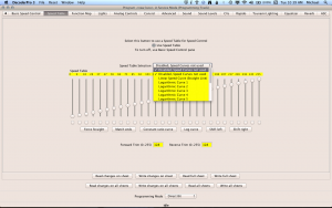
Decoder Pro allows access to the speed tables, and any options the decoder may offer.
There are a number of videos and tutorials on the web demonstrating speed matching using the speed tables in the multifunction decoders.
Notes on Various Manufacturers
NMRA S9.2.2 specifies all decoders provide CV2 (Vstart), optional are CV5 (VHigh) and CV6 (VMid). These three CVs are active when Bit 4 of CV29 (Speed Table Enable) is 0.
Speed tables are Optional, using CVs 66 (Forward Trim), 67-94 (Speed Table CVs) and CV 95 (Reverse Trim). These thirty CVs are active when Bit 4 of CV29 is 1. The disadvantage is any tweaking of starting or maximum speeds requires reshaping the entire speed curve.
Digitrax
Digitrax multifunction decoders provide the user-loadable speed table in the 28 and 128-speed-step modes. They are supposed to support kick start and forward/reverse loco trim, but these features may not work on some of their current decoders.
SoundTraxx
SoundTraxx sound multifunction decoders provide the user–loadable speed table in the 28 and 128-speed-step modes. They also support kick start and forward/reverse loco trims with the user-loadable speed table as well as with their optional built-in speed tables.
- SoundTraxx Tsunami decoders differ from the standard. When the speed table is active (Bit 4, CV29 = 1), the value in CV2 added to CVs 67-94 in the speed table, pushing it upwards. The advantage of this variation from the NMRA standard is that one can tweak the starting speed without reshaping the entire curve. The disadvantage is that it can effectively flatten the top end of the speed table if maximum speed is already high.[10]
ESU
ESU has an Autotune feature on some multifunction decoders. This feature tunes the BEMF CVs automatically when run. This should be done before attempting speed matching.
Read your manual first, as Autotune may overwrite some custom values and result in degraded performance. This is particularly true for Rapido locomotives.
Not all ESU multifunction decoders support the NMRA three-point speed curve using CVs 2, 5 and 6. The LokSound 5 DCC does support this feature. An easy way to determine if a decoder supports this feature is to write a non-zero value to CV6. If reading CV6 after writing a value to it returns a 0, speed curves are not supported.[11]
ESU V4 and Select Decoders
ESU V4 and Select decoders differ from the standard.
When the speed table is active, the values in CV2 and CV5 are not ignored, however they specify the actual VStart and VHigh to be used. Additionally, CV67 value is fixed (read only) at 1, and CV94 is fixed (read only) at 255. Therefore, one needs to fit the speed table's curve between these two fixed end points. The effective values in CVs 67-94 are compressed (in the decoder) so the actual curve always starts and ends on the values in VStart and VHigh. The advantage of this variation from the NMRA standard is the power to tweak both starting and maximum speeds without reshaping the entire curve, eliminating any possible multiplicative errors found in the QSI approach. The LokProgrammer and JMRI DecoderPro enforce these restrictions on CVs 67 and 94 so one knows what their speed table will really look like. Also, the minimum value for CV2 is 1, the the loco cannot be stationary at Step 1.[10]
Train Control Systems (TCS)
Train Control Systems multifunction decoders provide the user–loadable speed table in the 28 and 128 speed–step modes. They also support kick start in the user-loadable speed table as well as the built-in speed curve, but do not support forward/reverse loco trims.
QSI
QSI decoders differ from the standard. When the speed table is active (Bit 4 of CV29 is 1), values of CV2 and CV5 are not ignored. If either of CVs are a non-zero value, these become the actual VStart and/or VHigh, and the effective values in CVs 67-94 are compressed or expanded (scaled) by the decoder, so the actual curve starts and/or ends on any non-zero value in Vstart and/or Vhigh. The advantage of this variation from the NMRA standard is that one can tweak both the starting and maximum speeds without reshaping the whole curve. The disadvantage is if the speed table already covered a restricted range, the curve will be expanded, with possible integer multiplication errors producing glitches in the speed table.[10]
Designing a Speed Table
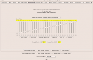
This procedure requires clarification, as it lacks details to explain how the end result was achieved.
This procedure is intended to create a speed table for a 28-step throttle where each throttle step is approximately equal to the locomotive’s scale speed in mph. This type of speed table is useful for a switching prototype and was specifically created for a model of the Alco S-2 locomotives used by the State Belt Railroad of California, a switching railroad that operated on the San Francisco waterfront between 1898 and 1993. In that service the prototype locomotive was typically operated between about 4 and 15 MPH for switching and urban street operation. The basic process used to create this speed table can be adapted to other applications.
Before You Begin
Fine tune the operation of the vehicle as much as possible with the speed table and other speed setting before using these specific features
Turn OFF (Set CV to a value of 0 (Zero))
- Momentum (CV3/CV4)
- Kick Start (CV65)
- Dither or Torque Compensation (see the manual for these CVs)
Tune the Locomotive
The creation of a speed table is very specific to a particular locomotive and its decoder and is therefore affected by various tuning parameters that can affect motor operation. Before attempting to create the speed table, do all necessary tuning both mechanically and with CV’s relating to motor operation. This is particularly important with respect to back EMF related CV’s. Once the locomotive is running to your satisfaction proceed with the creation of the speed table. This specific speed table was created for a Arnold/Rapido N scale S-2 model. The model was modified with North West Short Line 2679-6 geared wheelset. A Lenz Silver Mini DCC multifunction decoders was installed.
Gather Performance Data
AS this is just an example, there are no numbers or calculations presented. It is just an explanation of how to go about fine tuning a speed table manually.
It is useful to know what the minimum scale speed the locomotive is capable of starting at during DC operation. In the case of the above locomotive, it was capable of maintaining a minimum speed (DC) of about 6 scale MPH. It later turned out that with DCC and the back EMF parameters tuned it could maintain a scale speed of 1.5 MPH. It found that the linear-voltage performance followed a different curve below 6 MPH than it did above 6 MPH, presumably related to the DC capability and the operation of back emf. It will be explained later how to deal with that behavior.
The first step is to gather data on how the locomotive runs with a linear voltage curve. Select the standard speed table with the CV 5 Maximum Speed parameter set at 255 and the CV 6 Mid Speed Vmid parameter set at 128. These settings establish a linear voltage curve. Set momentum to 0. Set the throttle steps to 128.
Take speed data at throttle settings over the range of operation of interest. In this case data was taken at throttle settings of 1-6, 9, 14, 18, and 24. The data taken was the time in seconds required to travel 12” both in forward and reverse with the two figures added together to average the speeds. Typically, speed will be slightly different between the two directions. These throttle settings produced a range of speeds from 1.5 MPH to 31.2 MPH. Because the operating speed range was intended to be from 0-28 MPH, this is all the data that was required.
The throttle settings must be translated into internal digital values (ranging from 0-255) that are used to set to the decoder's voltage steps. Experimentation indicated that the very first throttle step corresponded to a digital value of 1 and thereafter each digital value was equal to 2X the throttle step. A table of digital values and scale speeds was thereby established
Analyze the Data
The digital values were plotted against the scale speed and the least squares fit established. It was observed that there is a kink in the data at about 6 MPH. This was dealt with by using two different linear data fits, one for below 6 MPH and one for above 6 MPH. Microsoft Excel was used for the plotting and least squares data fits.
The formulas for the two lines are used to establish the appropriate CV values for the speed table as follows:
The equation for a line takes the form: Y = MX + B
In this case X is the digital voltage step value and Y is the scale speed in MPH. To create the speed table, we need to be able to calculate voltage step digital values from desired speeds for each throttle step.
Simple algebra gives the following formula: X = (Y – B)/M
The least squares fit gave the following for the slope and y-intercept.
- Below 6 MPH: M = 0.4232, B = 1.0613
- Above 6 MPH: M = 0.6794, B = -0.4288
These values are used to calculate the speed table.
Calculate the Speed Table
Before proceeding though consider how the speed table is defined. It consists of 28 values that define voltage output at 28 equally spaced throttle settings from minimum to maximum. If you use a 28-step throttle, then each speed table value exactly corresponds to a throttle setting. However, if you use a 128-step throttle then each speed table entry corresponds to 128/28 = 4.6 throttle steps, which means the multifunction decoders will interpolate the intermediate throttle values. This complicates calculating a speed table and introduces greater inaccuracy due to rounding errors - specifically errors in speed vs throttle setting. Since this application only required a narrow range of speeds it was decided to use a 28-step throttle.
It was desired that each throttle setting would correspond as exactly as possible to the actual scale speed in MPH (i. e. that a throttle setting of 9 would correspond to a speed of 9 MPH). In this case then each respective speed table CV value should produce as exactly as possible the corresponding scale speed. The calculation is performed as follows:
(Y – B) / M = CV setting, where Y = Speed MPH, and M and B are selected from the appropriate speed ranges as noted earlier. Note that this formula will calculate a value that must be rounded to the nearest whole number. The formula calculates 0 for the first table CV value so the first value was set as 1. Neither formula calculates a sensible value for 6 MPH because of the kink, so an intermediate value was chosen. A set of values were calculated and entered into CV 67-94 creating the speed table.
Resulting Speed Table Accuracy
The speed table was tested using the intended 28 step throttle and delivered acceptable performance for the application of +16%/-10%. These errors were less than 1 MPH in most cases.
Some improvement may be possible by manually adjusting the speed table or recalculating CV values, taking into account an error function. However, it should be kept in mind that with the use of relatively coarse digital values there is a practical limit of accuracy in any speed table that is on the order of a 5% average error. The error limit at low speeds is even greater due to limitations of the motor.
Footnote
Speed tables must increase monotonically (i.e. no speed step can have a value lower than its previous speed step). Failure to do observe this restriction can cause strange behavior in some decoders, both the LokProgrammer and JMRI DecoderPro will prevent this. Share this page
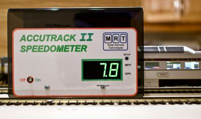
Speed Matching Using JMRI and Accutrack II Speedometer
Further Reading
- Multifunction Decoder
- Speed Matching Locomotives
- Momentum: Explains the disconnect between the throttle and prime mover
- Video: Speed Tables Demystified
- DecoderPro® Comprehensive Programmer - Speed Table Pane
- ↑ 1.0 1.1 Recommended: Strongly encouraged but not mandatory
- ↑ Optional CVs may be included at the manufacturer's discretion.
- ↑ Much the same as when you move your car's gear shift to Drive, it doesn't stall or surge when you press the accelerator, it runs efficiently at highway speed, and delivers maximum fuel when you floor it without surging or stalling.
- ↑ S-9.2.2: Vstart is used to define the voltage drive level used as the start voltage on the motor. The voltage drive levels shall correspond linearly to the voltage applied to the motor at speed step one, as a fraction of available rectified supply voltage.
- ↑ S-9.2.2: Vhigh is used to define the voltage drive level used as the start voltage on the motor. The voltage drive levels shall correspond linearly to the voltage applied to the motor at speed step one, as a fraction of available rectified supply voltage.
- ↑ A value of 0 or 1 indicates that VHigh is not used in the calculation of the speed table.
- ↑ S9-2.2: Vmid specifies the voltage drive level at the middle speed step. Vmid is used to generate a performance curve in the decoder that translate speed step values into motor voltage drive levels and is specified as a fraction of available rectified supply voltage.
- ↑ Values of 0 or 1 indicates VMid is not used in the calculation of the speed table.
- ↑ 9.0 9.1 S-9.2.2: Determines the decoder's acceleration rate. The formula for the acceleration rate shall be equal to (the contents of CV#3*0.896)/(number of speed steps in use). For example, if the contents of CV#3 =2, then the acceleration is 0.064 seconds/step for a decoder currently using 28 speed steps. If the content of this parameter equals "0" then there is no programmed momentum during acceleration. CV4 works in the same manner.
- ↑ 10.0 10.1 10.2 Dave Heap, Email on GroupsIO
- ↑ If a decoder does not support a feature, the related CVs cannot be changed.

