Pulse Width Modulation
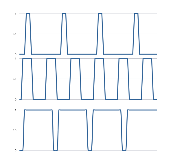
Summary: Pulse Width Modulation (PWM) allows better control of the motor. Rather than applying pure direct current to the motor, a series of pulses is used instead. They can be at the maximum power, but only for a fraction of a second. Doing this repetitively will cause the motor to begin to turn, producing torque. This allows slow speed operation in a more controlled manner. Simply applying a low voltage DC signal will not overcome the friction of the motor and gears, resulting in a jerky start, and poor low speed operation.
By varying (modulating) the pulse width and the frequency, slow speed operations are possible, and allow realistic operations in a yard.
The DCC multifunction decoder creates this signal to drive the motor.
This is the same process used in Switch Mode Power Supplies to control and regulate their output.
Technical Details
Why Not Use Direct Current?
While Direct Current is the most efficient mode of driving a motor designed for it, this technique is not suitable for DCC decoder technology. It is much more efficient to use PWM, as other methods waste power and create excessive heat in the process. It is very simple to implement PWM with a microcontroller and a few transistors. So, despite the advantages of direct current, the disadvantages are much greater.
Torque Versus Voltage
Pulse Width Modulation allows the DCC decoder to overcome issues inherent to the design of a DC Motor.
There is a tradeoff between voltage and torque. At low speeds, the torque/voltage curve is poor, resulting in a locomotive which will not run smoothly. Using a motor which is designed for lower voltage is one solution, at the expense of tractive effort.
To overcome that limitation, PWM is employed. By application of full voltage to the motor in the form of pulses, the slow speed operation of the locomotive was improved. The downside to this method was increased motor chatter and vibration. Most decoder manufacturers use a high frequency PWM signal to drive the motor. This overcomes the noise and vibration issues. There is some loss of torque, but most decoders employ a form of torque compensation to overcome that.
Benefits of Pulse Width Modulation
- Simplicity: The motor drive circuit is simpler with fewer parts needed to interface with the decoder's microcontroller.
- Power Efficiency: The induction of the rotor's windings will average the current flow (Inductors resist the change in current.) The transistors have low impedance, low voltage drop and power dissipation. A resistor dissipates a lot of power (I2R) as heat.
- Speed Control: The motor sees a low impedance current source, even as the source constantly switches between high and low voltage. The result is a motor which has higher torque. A series resistance will cause the motor to experience a very poor current source and will easily stall.
- Control Circuit: For digital electronics (such as a microcontroller) it is very easy to switch voltages on or off using transistors or FETs. An analog output (either electronically or mechanically controlled) requires more components and increases power dissipation, wasted as heat. It will be more expensive in terms of electronics and power requirements.
Voltage
The voltage available to the motor is a function of the track voltage. Since the DCC signal combines both the power and the digital signal, it stays at a fixed level. For example, when set to HO a command station will put about 14V onto the track. A couple of volts are lost in the decoder's power supply during conversion to a pure DC voltage.
If the track voltage is low, the motor will not get as much voltage, limiting top speed.[1] Which increases current consumption by the decoder. To limit the top speed of the vehicle, use the V High CV.
The voltage applied to the motor is of constant amplitude. Speed is controlled by the pulse width, which is adjusted using the V High to limit the maximum average voltage applied.
How Does it Work?
PWM is implemented by the decoder by switching the output to the motor on and off rapidly. This technique is very efficient with little power loss.
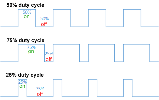
At a slow speed, full voltage may be applied to the motor for 20% of the time. The other 80%, it is off. This switching might be happening 1000 times a second. So, for one millisecond, the power is on for 200 microseconds (uS), and off for 800 uS. The effective voltage being applied to the motor averages 20% of Vmax. If Vmax is 13V, the average would be 2.6V.
At mid speed, the voltage might be on and off for equal time periods. Using Vmax at 13V, the motor would see a Vaverage of 6.5V. At full speed, it might be 1mS on and 100uS off.
Despite some CVs being named VStart, VMid, and VHigh there is no way to change the voltage output. Their names are not descriptive of what they really do. They allow you to set the output to start the motor turning at step one, adjust the maximum speed, and tweak mid-range operation. This is done by adjusting the duty cycle of the output pulses. Which controls the current flow through the motor, not the voltage applied.
Also see the article on Dither.
Back EMF and Sound
The PWM output is related to the BEMF, as the frequency will be altered by the BEMF values. This impacts sound, as the decoder can use these values to create appropriate loading sounds for a steam or diesel engine.
Issues
Heat and Demagnetization
While it allows the decoder to run cooler, the motor will run a little hotter. It also may not have as much torque.
This was an issue when Pulse Power appeared many years ago. There were concerns that the high frequency high voltage pulses would demagnetize the motor's field magnets. This was of particular concern in the early days of carrier control about the high frequency carriers having the same effect. Modern alloys seem to have conquered that fear.
Resonance
At certain frequencies or speeds, the motor and chassis may resonate, making an annoying buzz. Increased noise can also be caused while in operation, changing in amplitude and frequency with the speed.
Modern decoders minimize this by offering variable frequencies, many using supersonic frequencies above what a human can hear. (Your dog may get very annoyed.) Higher frequencies plus the ability to modify them can also be used to tune the PWM to minimize any resonance. Much like the tone controls on your hi-fi let you adjust the sound to your room and your preferences.
Some decoders may even use a dynamically changing frequency to minimize any resonance and improve torque response.
Benefits
Other than the previously mentioned heat issues, you get Back EMF!
When the power is disconnected from the motor, the decoder can measure the Back EMF generated by the motor. By monitoring the BEMF, it can make adjustments to control the speed accurately. This allows the decoder to change the modulation as needed.
Additional Reading
- Speed Steps
- Dither
- Back EMF
- Motor
- Simplex, Duplex and Infrared: PWM can cause interference with Radio Throttles, such as that emitted by dimmable LED lighting.
- Anti-Buzzing Circuit. This link has schematics for circuits to supress the noise from a low frequency PWM drive common in older multifunction decoders.
- Caveat: Only use with MOSFET output decoders. Some examples are: Digitrax DH140; Wangrow DH155, D104; North Coast Engineering N103, D107, D408; Lenz 103.
External Links
- ↑ Voltage equals speed, current results In torque in a motor. By controlling the direction of current flow, direction is established.


