Power District
Summary: A Power District is the preferred Digital Command Control term for what was, and is often called, a Block. In prototype railroad operations, a block is a section of track, usually controlled by signals. Block is a legacy term from the days of analog operation of model railroads.
An analog (Direct Current) controlled model railroad employs electrical blocks, which are sections of track that can be powered independently. This allows trains to operate independent each other by connecting separate throttles to individual blocks via a selector switch.
Digital Command Control doesn’t need blocks, as trains run independently on a single “block”, with the whole railroad potentially being one block.
Digital Command Control Power Districts
In Digital Command Control the term block is not used. The equivalent term is Power District.
With Digital Command Control, Power Districts are only needed when you want to split up the track for the following reasons:
- Create separate power districts so as not to overload a booster. This is done with power management devices
- Isolating sections of track (using a power management device) so a short circuit in one district doesn't shut down the entire layout
- Add additional boosters to increase the capacity of the layout to run trains
- Operational signaling
- When a track section loops back on itself, such as a Wye or Balloon track. A reverse section is a power district which is needed to prevent a short when the locomotive bridges the gap when returning to the mainline. An autoreverser will automatically match the phase of the two sections of track
- Block detection so you can determine where a train is, and
- Transponding or Railcom so you can tell what train is in a specific block
Power Districts are not needed to control the actual trains. That is handled by the multifunction decoder inside the locomotive.
It is important to gap both rails, and fill the gap using an insulated rail joiner or other material when creating a power district. Filling the gap is important to prevent one district from connecting to another should the rails move with the benchwork due to humidity changes.
Booster and Power Districts
Hierarchy of Districts
There are two levels of districts. The highest level is the Booster District. The level below it is the Power District
Booster District
Two boosters should never power the same segment of track. The boosters will be damaged.
- A segment of track fed by its own dedicated booster is called a Booster District.
- The Booster district can be the entire layout.
- The layout can be further subdivided using a power management device into two or more subdistricts called Power Districts.
- The addition of a second booster mandates that the layout be divided into two distinct electrical segments. Each one becomes a Booster district, fed by a dedicated booster.
- Each Booster district can be further subdivided into two or more Power Districts
Power Management devices and boosters should share a common return circuit. This allows current to return to its source, and must be a heavy gauge wire. Otherwise, currents returning to their source may use the throttle network.
The common return establishes a reference point as well as providing a path for currents to return to their source. The device should have a connection for this purpose, or attach the wire to the case of the booster if necessary. See DCC Wiring and Grounding.
The DCC system must be floating. Do not connect command stations, boosters or power management devices to earth ground.
Power District
A Power District is created when the track is divided into two or more electrically independent sections, with power supplied through a power management device. A booster feeds the power management device, which subdivides the DCC power and routes it to a Power District.
Should a short circuit occur within a power district, the power management device will disconnect that district from the booster. This prevents shutdown of the entire layout in circumstances like this. The rest of the trains keep moving as if nothing happened, and the cause of the short within the district can be remedied without impacting operation elsewhere.
Examples
Example Booster District
A yard powered by a dedicated booster. There may be an engine service area within the yard where motive power is sitting idle, as well as locomotives being hostled onto the ready track, awaiting their crew and a train assignment. The entire yard, with both switchers and road locomotives, may demand a significant amount of power.
By assigning a booster to supply that power to the yard, the rest of the layout will have more power available to it from another dedicated booster. A single 5A booster may not be able to supply the demands of mainline and branch line operations in addition to a busy yard and engine terminal.
Assuming ten locomotives idling on the service and ready tracks with two switchers working the yard, demanding 250mA at idle and 500mA when working, you would need 0.25 × 10 + 0.5 × 2, which equals 2.5A + 1A, or 3.5A. That is a significant demand on a booster.
Giving the yard its own dedicated booster reduces the burden on the entire layout. It also isolates the yard from the layout, eliminating interruptions created by derailments or incorrectly aligned switches in the yard.
Reverse Loop as a Booster District
It is possible to power a reverse loop using a dedicated booster. The loop must be isolated from the track leading into it, and if the booster features auto-reverse, that must be disabled. The phase relationship between the boosters can only be controlled by one booster, this allows autoreverse to function correctly. See the example below in the Power District section for more detail.
Example of a Power District
In analog schemes, a switch selects which throttle controls the block. In DCC, throttles control the trains.

A Reverse Loop is a type of power district.
For proper operation, a reverse loop must be isolated from the trackage leading into it. Otherwise, a phase mismatch occurs at the turnout's frog, which will trip the circuit protection when the locomotive enters or exits the loop. A manual switch could be used to maintain the correct phase relationships, or a device such as an Automatic Phase Inversion unit. Unlike analog control schemes, in DCC the phase relationship has no bearing on the direction of travel.
By breaking the connection between the main trackage and the reverse loop by gapping the rails after the turnout, a power district is created. All the trackage is fed by the same booster. A device is inserted between the power bus and the loop's feeders, allowing it to maintain the loop's phase relationship. Then a wheel shorts across the gaps as the locomotive leaves the loop, the autoreverser senses this and corrects the phase relationship. The train continues on its journey as if nothing happened.
Another example would be the use of a power management device between the booster and the track. Instead of one power bus, there would be several, feeding independent segments of track. This method prevents an electrical event on one segment from shutting down the entire layout. This is similar to the concept of blocks with analog control schemes, except the purpose is to manage short circuits.
Direct Current/Analog Operations with Blocks
In Analog (Direct Current) model railroads, a block is a defined as an electrically isolated section of track. This allowed each section of track to be electrically and mechanically separated from the others, with power to run a single train from the throttle controlling that block. This resulted in complex electrical switching when a train moves from one block to another. This was required to insert the desired throttle between the power supply and the track. The arrangement can be as simple as a switch to select which block the throttle controls, or one that requires the operator to select both throttle and block to route power.
The operator or dispatcher would flip switches to route power from the selected throttle to the blocks the train needed to travel across. Ideally the switches would only allow one throttle to be connected to a given block at any time. In many cases the train would stop when the throttle was moved from one position on the layout to another.
- Basic Analog Setup with a Single Block and Analog Controller
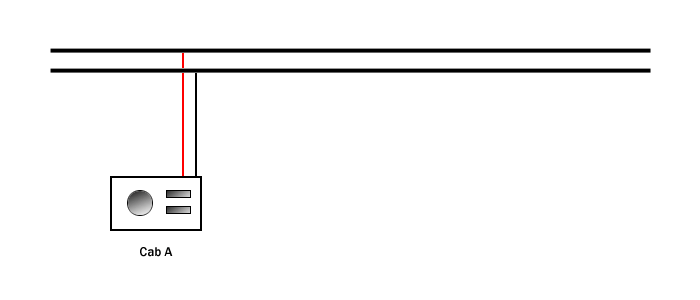

Wiring complexity is determined by how many blocks and throttles are in use, and the setup for operations. A central dispatcher may control the power routing on a large layout or in a club setting, or throttle selection could be more local to the operator. In any scenario, it means a lot of wire, many switches, and significant investments in time and money. Digital Command Control eliminates the need for complex wiring to control train movement.
- Two Cabs Controlling a Length of Track Divided into Blocks
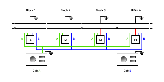
As shown by this example of analog control, switches (T1, T2 and T3) are used to route power from the selected Cab to a Block. As the train progresses, blocks will be connected and disconnected from the cab. This example shows two Cabs controlling trains independently using blocks and switches to connect them to their trains.

Planning Power Districts
The best way to determine where to locate a power district is by examining the traffic and power requirements needed for each operational section of the layout. A busy yard may have several switchers in motion, multiple locomotives on the standby tracks, a locomotive servicing area, and trains arriving and departing regularly. There may even be a local freight or two serving nearby industries.
A long stretch of mainline may only have one or two trains on it, with a few sidings and branch lines. There probably will not be a lot of traffic demanding power, but consideration should be given based on track density. A double track mainline may see a lot more traffic, thus it would require more power to operate effectively.
By subdividing the track into power districts, a power-hungry zone such as a busy yard can be divided into one or more power districts. Having the yard as its own power district will eliminate annoying shutdowns cause by short circuits, which are inevitable where a lot of turnouts are found. A short in the yard would be isolated from the rest of the layout, allowing operations to continue unimpeded.
Should the need arise, a power district that demands a lot of current can be powered by a dedicated booster later to support the traffic in that district. Typically, a 5A booster can support up to 10 operators on a layout, depending on the amount of motive power in use.
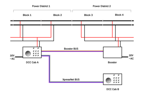
Power Districts driven by two Boosters. Cab A is a combined command station and booster.
Multiple Power Districts with Power Management devices.

Booster and Power Districts


See Also
- Track work - Main article on track work.
- Power Management