Troubleshooting LocoNet Issues
Summary: While LocoNet is rather simple in implementation, there are a number of issues which can occur.
Troubleshooting LocoNet
Also see the Digitrax Hints page for a list of Audible Alerts
Construction Issues
Many LocoNet problems are not really a LocoNet issue, but mechanical or electrical issues with the cabling.
Break in LocoNet Signal
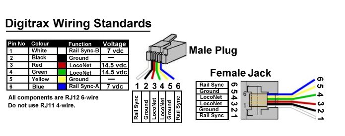
One issue is that the LocoNet signal from the command station is only present on one of the two LocoNet (red and green) wires. Usually the command station provides the LocoNet signal on Pin 3 (the red wire). At some point a device, such as a throttle, will bridge pin 3 to pin 4.
Devices such as a throttle, the LNRP or a UP92 will provide this bridge. The DT400 is known for not bridging pins 3 and 4. Another culprit is the UP5.
The LT5 LocoNet Tester can be used to determine if bridging is taking place, and then be used to find out where the bridging is occurring. It can also determine if the LocoNet signal is on the red wire before the bridge.
If a downstream booster stops responding, it is possible there is a break in the wires carrying the LocoNet signal from the command station. If there is a utility panel connected between the command station and the booster, and this problem only appears when a throttle is unplugged, one of those cables has an issue. Removing the throttle from the panel disconnects the bridge between wires three and four on the LocoNet cable.
If there are multiple panels between the command station and the booster, any one of those panels can be used to bridge the two LocoNet wires. Using a throttle, you can isolate the cables involved by testing each panel until the issue appears.
If there is no command station on the LocoNet, a LocoNet termination can also connect lines 3 and 4.
Crimping Issues
Improperly crimped connections are common. It is important to use the correct type of connector and a quality crimping tool.
There are two types of RJ connectors available on the market depending on the wire type:
- Solid Wire
- Stranded Wire
Using a solid wire RJ connector on a stranded wire may work, but it is not reliable. If it were, there would only be one RJ connector for both types of wire. Using a connector meant for stranded wire to terminate a cable with solid conductors will introduce issues as there are two prongs which penetrate the insulation, resulting in the potential for the wire to break at that point. Nicks in solid wire weaken the wire at that point.
Incorrectly crimped terminations may result in a cable which "tests good" with an LT1, but will not work with LocoNet devices.
Troubleshooting a LocoNet Cable
Using a DMM, measure the voltages on the cable, referencing the Ground terminal on the command station.
- A healthy working LocoNet should have 10V or more available between ground and pins 3 or 4 of the RJ connector.
- A cable with a poor, high resistance connection will see a reduced voltage on the pin(s).
- The voltage should be 9 to 10V on those pins.
RailSync
The RailSync wires (the outer pins on the RJ connector) can become an open circuit, without having an adverse effect on many of the devices they connect. RailSync is a low voltage/low power representation of the track signal. Your DMM can pinpoint the issue. These signals are not in phase, so do not short them together.
Digitrax Zephyr Specific
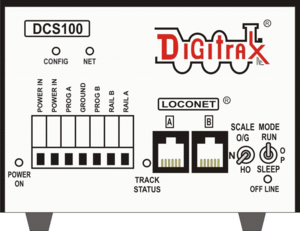
With a DCS100 integrated command station/booster or DB150 booster, only one of the LocoNet wires (3 and 4) is driven. Connecting a throttle bridges them.
In most LocoNet implementations, the two LocoNet wires are paired together. Throttles, DS54s, and the LocoBuffer all pair pins 3 and 4.
In some situations, this may not happen. Should a LocoNet device not work, this can be the issue. A common culprit is the DCS series Zephyr when connected to LocoNet devices. A Zephyr internally connects the two wires via a resistor. The devices do not work as the signal is missing.
The solution can be a shorting plug, made from an RJ connector. A wire is fitted to connect between pins 3 and 4, which is then crimped in place. The shorting plug can then be inserted in any available spare LocoNet jack, which should resolve the problem.
LocoNet Termination Issues
LocoNet Termination for this discussion refers to the supply of power to the Rail Sync lines. If you are looking for terminations on a power bus, please refer to the Bus Termination page.
Some devices may not work if the LocoNet is not terminated correctly. Many LocoNet devices rely on the RailSync wires for power. A low current 12VDC source can supply this for a standalone LocoNet. Another function of the termination device is the connecting of pins 3 and 4 together. For a standalone LocoNet implementation, a small 12V power supply is used to provide power to the Railsync lines.
A number of devices, such as the PR3 can provide LocoNet termination.
A Utility Panel can also supply power on the Rail Sync lines.
Digitrax LT1
- Main article: LT1
The LT1 is included with all Digitrax Starter Sets. It consists of a harness with 6 conductor Telco type wire and a male plug, a tester with a female 6 conductor jack and a protection resistor. The LT1 can be used to test LocoNet cables, as well as multifunction decoders. While it is basic, it can indicate the motor control is working, as well as functions.
Rail Sync
Low voltage RailSync signals are present on the cables. Check for them using the LT1. The two outer LEDs must be bright, and constantly lit. If not, work your way through the network until the offending cable is located.
For proper operation of the booster, all four LEDs should be lit.
- This is not the same as a booster phase issue.
DCS100/DCS200 Command Stations
The NET indicator on the DCS100/DCS200 Command Station is a Red LED that displays information about what the Command Station sees on LocoNet. When your LocoNet is wired and operating properly, the NET indicator will be on and flickers any time a valid LocoNet message is detected by the Command Station. The following table explains the various patterns for this indicator:
- Solid Red
- OK
- ON, Blink OFF
- Valid LocoNet Message detected.
- OFF
- LocoNet is possibly shorted
- Blinking every half second
- The command station is in Option Set mode.

