PECO Insulfrog
Summary: The PECO Insulfrog turnout is DCC Ready right out of the package. Much has been written about the Insulfrog and DCC, yet a simple additional step during installation will solve all the problems.
Part of a series on turnouts or track switches and Digital Command Control
- Main article: Turnout
PECO Turnouts
PECO manufactures a number of turnouts in various scales.
- The Insulfrog, subject of this article
- Electrofrog,
- Unifrog, a new product which is intended to replace the Insulfrog and Electrofrog products. These products will be gradually phased out and replaced by the Unifrog line.
Insulfrog
The PECO Insulfrog is a power routing turnout. The term Power Routing indicates that only the route selected by the switch rails has power. This is accomplished by controlling power to the point rails. Out of the package it is 100% DCC Compatible. For existing installations, modifications may be needed to eliminate a source of problems associated with the design of the frog.
Thanks to Railway Bob for the information and permission to use it.
Also see the PECO Electrofrog page.
If you have problems with a particular vehicle equipped with metal wheels causing shorts when travelling through an Insulfrog or Unifrog turnout, you should begin by checking the wheel gauge and turnout clearances using an NMRA gauge appropriate for your scale. One culprit is the lack of a 3º taper on the wheel's tread.
Description
The PECO Insulfrog is DCC Ready right out of the box!
As one can see in the images below, the Insulfrog is considered "DCC Ready" as the switch/closure rails are electrically connected to the stock rail nearest to them. Unlike the Electrofrogs the Insulfrog controls the flow of electricity to the routes that come out of the turnout (Power Routing), energizing the appropriate point rail.
With DCC there is a potential shorting problem as metal wheels go through the frog. This only occurs if the wheel lacks the 3º taper recommended by the NMRA. Wheels manufactured for the European market do not seem to have this problem.
On analog/direct current layouts, the Insulfrog was often employed for its power routing ability to isolate a siding. In DCC practice, all track is energized all the time from the power bus. This is where the shorting issue comes in. The momentary short can trip the booster or restart the decoder. This problem occurs particularly with the PECO Medium and Large Radius Turnouts.
Insulated rail joiners on the point rails solve the common issues found with DCC and Insulfrogs. They eliminate the potential for short circuits occuring at the heel of the frog and between the stock and switch rail. When converting existing trackwork to DCC, follow the instructions presented here to identify and correct any issues which arise.
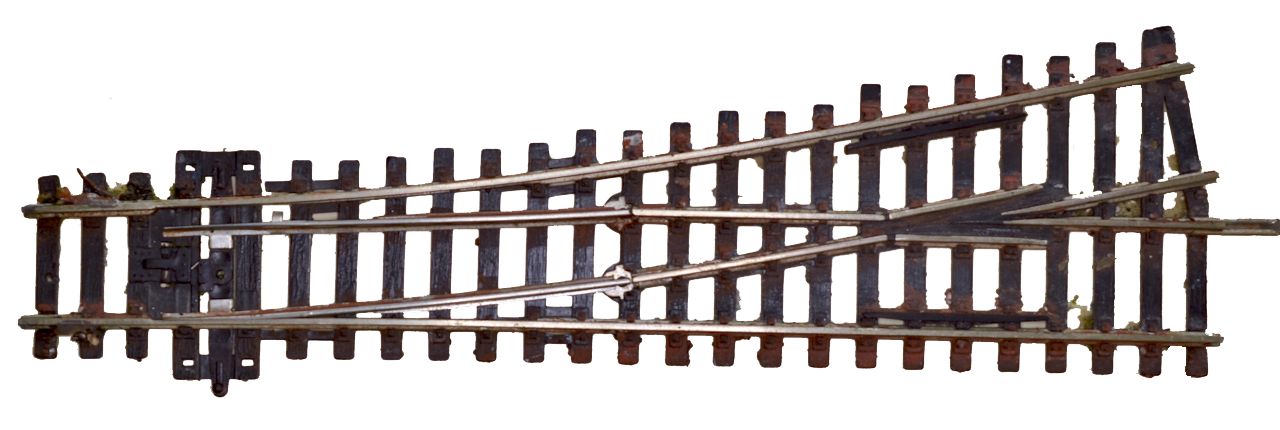
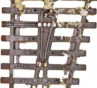
A PECO Insulfrog. Note the tabs on the switch rails, which control power routing. The fog is cast plastic, which insulates the closure rails from the point rails.
The PECO Insulfog functions just like an electrical switch: Tabs under the switch rails route power to a closure rail, through wires under the frog, then to the correct point rail. A spring under the cover above the throw rod keeps the switch rails latched in position.


The usual source of frustration with turnouts and DCC is when the switch rails are electrically bonded together and a metal wheel bridges the gap between the open switch rail and the stock rail. The Insulfrog's switch rails are independent of each other, with the electrical connections made by a tab, as seen in the picture above.

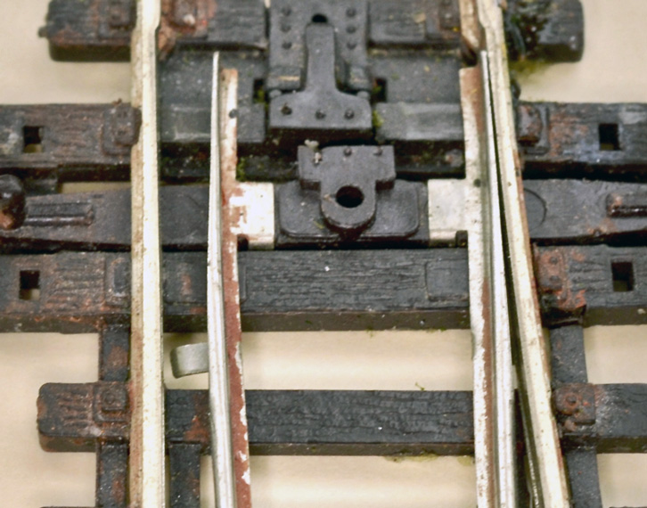
Details of the PECO Insulfrog. The frog is cast plastic, so it is non-conductive. The metal wing rails are also unpowered. Note that gap filled with plastic on the left isolating the closure rails from the wing rails at the toe of the frog. Wires beneath the frog carry power from the closure to their associated point rails. Which point rail is energized is determined by the position of the switch rails which power their closure rails. There is no electrical connection between the stock and point rails outside of the switch rails. On larger numbered turnouts the point rails at the heel of the frog can be bridged by a wheel tread, creating a short circuit.

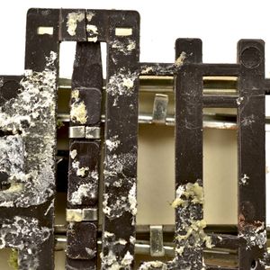
These tabs on the underside of the switch rails electrically connect it to the stock rails. Power is then available on that switch rail, and through the closure rail is supplied to the appropriate point rail. This is how the power routing is done.
Wiring on the underside of a PECO Insulfrog connecting the point and closure rails
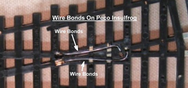
Wiring on the underside of a PECO Insulfrog
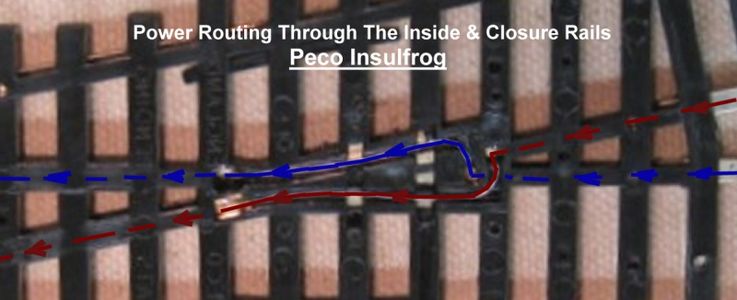
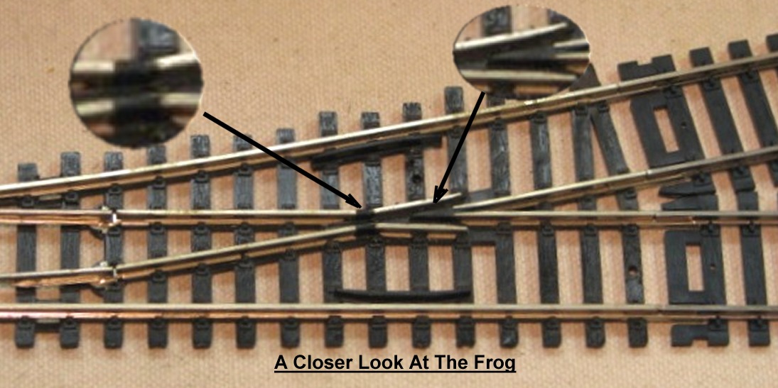
Power flow across the frog of an Insulfrog


As shown in the pictures, the point rails are powered using small wires which bond the appropriate point and closure rails together.
The DCC Problem: With an Insulfrog the two point rails converge forming the heel of the frog, with a small plastic filled gap between them. A metal wheel can bridge across the gap, causing a short. Adding insulated rail joiners helps, as per DCC practice all trackage is energized from the power bus, not the switch rails. Meaning the Insulfrog's switch rails are not controlling the point rails, as they are being powered by the downstream trackage connecting to the point rails. Doing so will give control of the point rails back to the switch rails.
Insulated rail joiners on the point rails also eliminate the possibility of a short between the stock and switch rails caused by a metal wheel, as they would not be back fed from the point rails.
Electrical Issues
Short Circuit Caused by Wheel on Point Rails
Often caused by an improper wheel profile, such as flat wheels and blind drivers. NMRA RP-25 illustrations of the wheel show a 3° taper on the tread face from the fillet radius, which aids in tracking. Unfortunately, the 3˚ taper is not mandatory. The NEM (European) standards require wheels to have this taper.
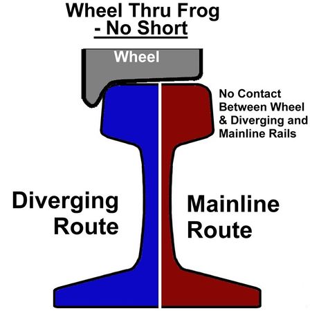
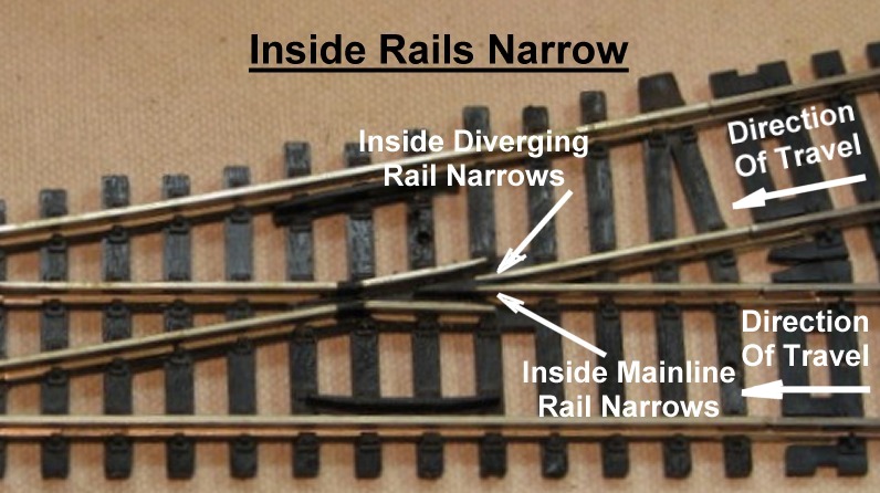
As the wheel moves from the mainline or diverging route into the frog and toward the switch, the distance between point rails narrows until they terminate in the plastic heel section of the frog. While this narrowing is not obvious in the photo, it is very obvious with large numbered turnouts.
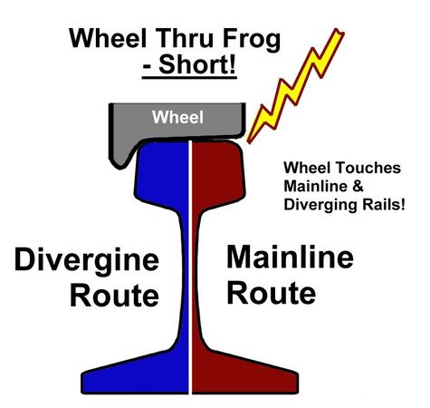
In the diagram, as the wheel travels along the point rail, it begins to overhang the other point rail.Getting closer to the heel of the frog, the wheel can bridge across the gap between the energized point rails. These rails are out of phase. A short occurs when the wheel bridges both rails and the command station/ booster shuts down. A wheel with a 3º taper should not cause this issue.
Where the point rails meet at the heel of the frog a short can occur when a wheel tread lacking the 3º taper bridges the two. Insolating the point rails using gaps and controlling power routing with a switch machine helps to eliminate this issue.


Insulfrog Modifications
Thanks to the mythology surrounding the Insulfrog, many modellers forego the necessary addition of gaps to the point rails. When shorts occur at the heel of the frog the advice offered is add paint, such as nail polish, to the rail head. While this solves the shorting issue, it is temporary as the insulating layer of paint will eventually wear off. Other solutions are even more extreme. The best solution is to add gaps to the rails, which while difficult is not impossible once the turnout is installed.
The power routing capability of the Insulfrog was useful in analog operations, but a source of problems with DCC since the turnout no longer needs to control power routing. With the use of insulated rail joiners on the point rails, the Insulfrog will work flawlessly.
Once the turnout is installed making corrections to the installation isn't easy. Prior to installation, insulated rail joiners installed on the point rails allow the switch rails to control their respective point rail, which eliminates the wheel bridge issue as only one point rail will be energized. Downstream trackage is not providing power to the point rails. This method also eliminates the possibility of a short caused by a wheel bridging the gap between the switch stock rails.
If this issue is discovered after installation, cutting gaps in the point rails will solve the problem. Now the DCC signal on the point rails is controlled by the switch rail's position. Without isolating the point rails the track past the heel of the frog will be powering the point rails, eliminating the power routing feature of the Insulfrog.
If a gap is cut, insert an insulating material, such as styrene, to fill the gap and prevent a problem should the gap close due to movement of the benchwork and/or rail expansion caused by humidity and temperature changes.
Only one point rail is energized, and that is controlled by its associated switch rail.
Booster Changes
With some boosters it is possible to slow the reaction time when a short is detected. By increasing the timeout value nuisance trips can be reduced, such as those caused by the wheel tread bridging the point rails. See the instruction manual for your booster for details.