No Common Rail Wiring
| Basic wiring |
|
| Track wiring |
|
Summary: Common rail wiring was often used with analog control, as it reduced the amount of wire needed, and the complexity of the circuit. With DCC, it introduces new problems.
Overview
When wiring a layout, there generally two ways to run the wires: common and un-common (home-run wiring). Common rail wiring can be used on small layouts but do not be tempted to use the same method for medium to large DCC projects. A few key rules and recommendations for wiring a DCC layout:
- Do not use common rail wiring.
- Do not connect any of your booster outputs together as this can cause shorts to occur, or boosters fighting one another. Even worse, if one booster should flip phase both could be damaged or destroyed.
- Connect the grounds of boosters together.
- Either via the case or a connection labeled Ground (see your manual). If you have more than one booster this is needed to provide a current return.
- Do not connect the booster to earth ground! The layout wiring should never be connected to earth ground for safety reasons.
- Common rail wiring makes troubleshooting more difficult if there is a wiring issue.
- Additional boosters or power management devices cannot be used with common rail wiring.
Most manufacturers tell you not to have a common rail or common power bus wiring between booster or power districts. This is just here to help them make the point clear. Gap both rails whenever you make a gap. Do not connect any power or programming wires from one booster output to another's output. From NMRA Data Sheet D7p: Common Return Systems
- This single return conductor can handle both the Common Power Return system and the Common Rail Return system simultaneously, if desired. However, this combined system is not recommended if a Command Control System is to be utilized. It appears that Command Control performs better when it is isolated from all other systems.
- Also, some block occupancy indicator systems perform better and are less sophisticated if they are located in the non-control rail feeder. This means that common rail is not recommended here either.
If you have an existing analog (DC) layout with common wire/rail and want to convert to DCC, then unless the layout is small, you will want to consider gapping your track and cutting the common wire. You should also examine the wiring and upgrade as needed to DCC standards.
If you have an existing analog (DC) layout that isn't using common rail wiring then you could use the wiring as-is with each block becoming a booster district. But the main reason for blocks before (train control) is not the same as the reason for booster districts now (power distribution), so you may still want to review the wiring layout. You may have more blocks than you want as booster districts, in which case you can tie some blocks together.
Note: It is recommended that the wiring be brought up to DCC standards. See Converting To DCC for more details.
NMRA Data Sheet D7m does not recommend using a common return with command control systems. Use with block occupancy systems is not recommended either, for reliability and easier implementation.
Track Loops
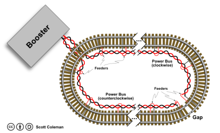
If you only have one booster on your layout, and the track is configured as a loop, you should split the loop both physically and electrically. This is accomplished physically by gapping both rails, and electrically by installing two buses to supply power to the rails, one clockwise from the booster, and the other counterclockwise. The gap location should be chosen such that the wire lengths of the clockwise and counterclockwise power buses are equal. Your bus wires will run along the track from the booster toward this gap in either direction and will end there as well. Instead of being a closed loop, your mainline will be wired as an open loop.
Rail joiners are not shown in the illustration: the gap itself is bridged by insulating rail joiners, and as always, feeder wires are run from the power buses to each rail segment, rather than relying on rail joiners to supply power across your layout. Power buses are illustrated as twisted pairs. See the Wire Sizes and Spacing article for discussions on twisting your bus wires.
It is now common practice in the DCC community to wire track loops as open loops rather than closed loops. There is however an ongoing debate on this issue, raging since the early days of DCC. Some systems may have problems with a continuous loop, whereas NCE claims their system will have no issues with a closed loop. Your Mileage May Vary.
Ground Connections
In the booster district wiring section, you will read that you should connect the grounds of your boosters together. This is different from connecting your booster outputs together, which you should never do! The grounds of your boosters should be connected together. The ground terminal is usually connected to the chassis, and serves the purpose of providing a common reference level between components such as boosters, command stations and power management devices. It also provides a return path if your boosters are out of phase when a locomotive crosses into the next power district.
- Do not connect the Ground terminal to the ground of your house wiring. Bad things can happen. Modern power supplies provide a ground terminal as well, which is not connected to the high voltage side of the power supply. This is for safety as well as a reference point, connecting your equipment to the house ground (or earth) will defeat the purpose.
- The terminal labelled "Ground" is in fact a Common.
- The Common connection between boosters, command stations and other devices (such as power management devices) serves to create a common reference for 0 Volts for all the devices.
- The Common can also serve as a return path between two boosters if excessive currents flow during an out-of-phase transition between booster districts. Very important with Digitrax's LocoNet, as the LocoNet cable cannot handle large currents which are looking to return to another booster.
- Connecting the low voltage side of your DCC system to the house ground (or earth) serves no purpose. In fact, it can introduce voltages and currents which have the potential to cause problems.
- Do not create a loop in the common/return wiring.
- If you have booster districts, the booster common should be connected in series with the booster before and after it (Daisy Chain).
- The current return path via the "common" connection should be directly between two boosters. Use a heavy gauge wire between devices. Use a different colour wire, so it can be identified as a common and not power bus wiring.
- Do not create multiple return paths. Doing so creates a "ground loop."
- If you have booster districts, the booster common should be connected in series with the booster before and after it (Daisy Chain).
Background
Most model railroads begin with the around-the-Christmas-Tree loop of track. The usual setup includes an analog (DC) power pack, track, an engine, and a short string of cars. If the bug bites, and a hobbyist is born, the layout quickly expands to take over the entire living room or dining room, at which point it is quickly banished to the attic, basement, or garage.
As the layout continues to grow, the voltage drop between the power pack and the far end of the layout results in a slowdown as trains move away from the connection from the power pack; they accelerate as they approach it.
The easy solution is running a second connection (feeders) to the far end of the layout. This bypasses all of the rail joiners and (usually) results in more uniform speeds.
When the layout grows large enough and more tracks are added, the next goal is to run more than one train at once. The simple solution, just putting 2 trains on the track, is problematic- unless there is a double-track main line, one train will catch up to the other, or pull away, requiring the intervention of the Big Five-Hook Crane to slow down the faster train.
Although a lot can be done with power-routing turnouts, it usually just lets 2 trains take turns on the layout. It's not true two-train operation.
Analog (Direct Current) Solution
With analog the solution requires a second power pack and some electrical work. Since only one power pack can be connected to a track at a time, the layout must be divided into multiple isolated sections of track. These are called 'blocks.' Each block is electrically insulated from its neighbour.
Block divisions are normally at 'logical' places, such as a section of main line with one or two sidings; a length of mainline with a passing siding may have two blocks: one for the main, and one for the siding; a long chunk of main line with no other tracks; various sections of a yard (inbound, outbound, classification tracks); or an engine terminal (engine storage, maintenance tracks, roundhouse, etc.). It's all up to you and your operational needs.
Electrical toggle switches route power from one power pack at a time to each block. Two power packs allow two trains to run at once. Although layouts with two power packs are most common, some layouts have more than two power packs, and allow one train to run for each power pack.
Two Ways to Wire Blocks (DC)
There are two common methods of dividing the track on a layout into "blocks": Common Rail and Un-Common Rail (Home-Run) wiring.
Although Common Rail wiring tends to be popular (perhaps because the electrical switches cost a bit less), it is NOT for use with Digital Command Control (DCC) layouts.
There are distributed power control schemes (where power packs are located around the track layout), however, in this example the controls are centrally located at a control panel. The connections are described in terms of Analog (DC) power packs, then the differences for Digital (DCC) power are noted.
Common Rail Wiring
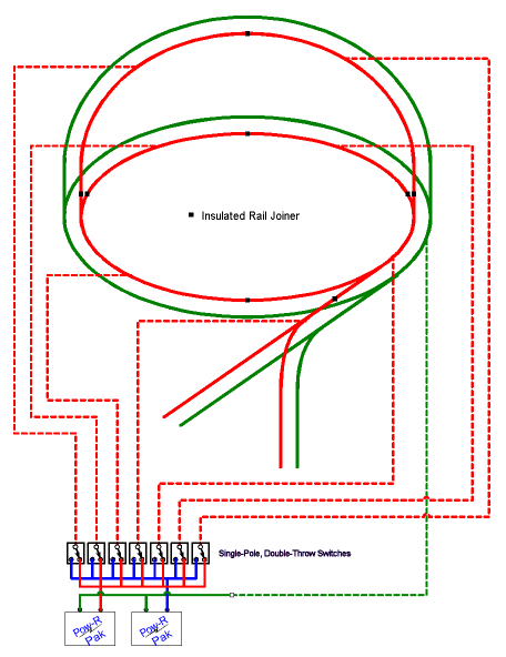
Common Rail Wiring is so named because one rail throughout the entire layout is unbroken – it is "common" to the entire layout (and all power packs). The common rail is constructed and wired so that it is electrically connected everywhere it goes (except reversing loops!). One terminal of each power pack is designated the "common" terminal. It doesn't matter which one you select, although if the power packs are the same, it is usual to select the same terminal on each pack. The Common Terminals are connected to the Common Rail. You connect all of the Common Terminals together, then connect the wire to the Common Rail of the layout. Depending on the size of your layout, you may need several connections to the Common Rail at various points around the layout to avoid voltage drop.
The remaining rail is broken into electrically isolated blocks. At the selected block boundaries gaps are cut in the non-common rail. To prevent problems due to expansion and contraction randomly connecting the 2 ends, either standard insulating rail joiners are inserted, or the rail is cut and a dab of glue (epoxy, Ambroid or 'goo') is dripped into the gap to prevent the cut ends of the rails from ever touching. Once the glue has cured, remove any excess glue from the top and inside of the rail.
Wires run from the isolated rail in each block to the control panel. You can use commercial rail contacts, or solder feeders to the rail. Switches connect one of the power packs to the isolated block rail. Single-Pole Double-Throw (SPDT) switches do the job with a two power pack setup. You need one switch for each block. This gives a single power pack control of the trains in that section of track.
Any power pack can use its reversing switch and speed control to guide trains through the selected block.
Un-Common Rail Wiring (Home-Run Wiring)
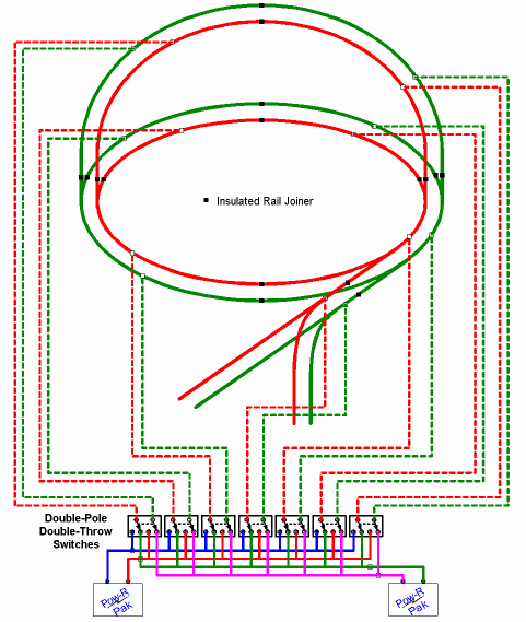
Un-Common Rail/Home Run Wiring is similar to common rail, with the following differences:
- Gaps are cut in both rails at each block boundary
- Wires run from each isolated rail in each block to the control panel.
- Double-Pole, Double-Throw (DPDT) switches are used to route power from the power packs to the blocks, instead of the SPDT used in Common Rail wiring.
- The term Home Run will be used to indicate the "Uncommon Wiring" technique.
Analysis
- The problem with either type of block control is that only one power pack can control a train at a time. Each block must be switched to 'your' power pack as your train approaches so that you can continue controlling your train. Multiple switches must either be placed around the layout, near the block they control, or a Master Control Panel must be created and manned during operations.
- Un-Common Rail (Home-Run) wiring requires Double-Pole Double-Throw (DPDT) switches to control power to the blocks. These are usually more expensive than Single-Pole Double-Throw (SPDT) switches. Good quality switches can be costly as well.
- Un-Common Rail wiring requires 2 wires to each block. The extra cost for wires may not be as much as you think-- many Common-Rail layouts require multiple feeds to the common rail to prevent voltage drop at the far points of the layout.
Switching to Digital Command Control (DCC)
- * When everyone starts talking about the advantages of Digital Command Control for your model trains, one of the advantages that keeps getting mentioned is "...you won't need to wire your layout in blocks!"
- * And then people start talking about "power districts" and "reversing districts." They're still talking about blocks! (DCC terminology for blocks).
- * Power Districts require blocks-- using Home-Run wiring, i.e. insulating gaps are cut in both rails at the block boundaries. This is one advantage to wiring your layout without common rail wiring from the start.
- * Switching from block control to digital requires you to
- ** Remove the block control electrical switches
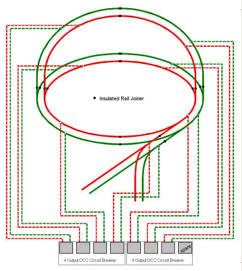
- ** Wire the wires from the block to a Digital Circuit Breaker Power Distribution unit. This lets a mishap in one power district stop the power to just that district; the rest of the railroad keeps running.
- *** For reasons of cost, multiple blocks are usually combined into one larger power district. If desired, the layout can be divided into multiple power districts using power management devices. For example, a yard may be one district, and the mainline another, so a short in the yard is isolated to the yard only.
- * Verify your wiring using the Quarter Test. This will identify any problems early.
Wiring In Anticipation of Digital Command Control (DCC)
- Divide your layout into blocks
- Wire using home-run wiring
- Don't be afraid of blocks! You can create lots and lots of blocks, run the wires to the control panel, and if you decide that two blocks should be a single block, you just join the wires from those blocks together.
- You can wire the blocks using un-common rail (home-run) wiring, and still wire the control panel as common-rail-- just hook all of the 'common' rail wires to a bus wire (see below), and wire the panel with SPDT switches. You save money on the switches, and you're still ready for digital.
- Use heavy gauge wiring to begin with, as if the layout will be DCC right now. This solves problems related to inadequate wiring later, and the expense of doing it again. A common problem during conversion is inadequate wiring that is not up to DCC standards.
Keep it Neat
Regardless if you are using analog or DCC, your wiring must be neat and organized! You just do not twist the wires from the layout together in a knot and hope the electricity flows!
- Use barrier (terminal) strips to connect your wires.
- A cheap alternative is to create a local 'bus' wire – take the bare copper ground conductor from a piece of non-metallic building wire (such as Romex brand). Place two screws in framework of your layout, wrap a length of the bare wire between the 2 screws.
- Solder your wires to this bus wire-- leave room between them, and twist the wires around the bus at least once – soldering the next wire could loosen the previous wire. This will keep the wires neat, and costs a LOT less than terminal strips!
Also, pick a colour code for all your wires, and stick to that colour code no matter what.
- Another option is coloured electrical tape. Just wrap the tape around each end of the wire to indicate which one it is. (Electricians will do that if they need to use another wire for a circuit which is not the correct colour.)
See Also
- Wiring - Primary Wiring article.


