Wiring Your Layout
| Basic wiring |
|
| Track wiring |
|
Summary: The approach you'll take will depend on what type of project you are attempting. This page is intended to steer you in the right direction. As you read this article, and other Digital Command Control wiring articles, you will find that wiring for Digital Command Control is always easier than the wiring for analog cab control.
|
See the Video. |
Layout Wiring for Digital Command Control
Successful wiring for Digital Command Control is a process.
- Larger layouts will need additional booster(s) to power more trains.
- Detection blocks to determine where trains are.
- Transponding for advanced computer train control.
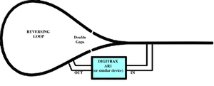
- reverse sections for reverse loops.
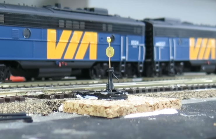
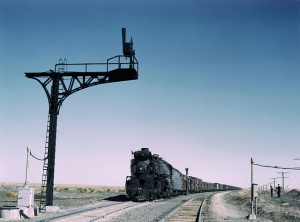
- Signaling for realistic operations
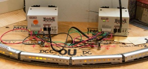
- Connecting a Computer to Your DCC System for computer assisted programming or complete computer control of your layout.
Selection of a Proper Wire Gauge
- Main article: Wire Sizes and Spacing
This is important for all sizes of layouts. Smaller layouts with short power bus runs can use a lighter gauge wire, but larger layouts with longer bus runs demand a heavy gauge for the bus wiring. Another factor is how many operators will the layout have. If only a few trains are in use with one or two operators on a small layout, the demand for power will be much less. On a large layout with many operators and many trains in motion at once, more power will be needed. This not only impacts the wire gauge used for the bus wiring, but also will require additional boosters, and creating booster districts. When wiring a large layout, managing the impedance of the power bus becomes very important, so proper selection and installation are requirements.
Workmanship
Careful and consistent wiring with workmanlike properties will be easier to troubleshoot, and less likely to for mistakes to occur during the wiring phase. Use quality tools and materials, and approach the process with the intention of creating a consistent result. Pick a colour code for each layer of wiring to assist in the initial wiring and any future changes or troubleshooting.
Wire Routing
Route the wiring so that it is not only easy to access or work on, but also try to follow the track as much as possible. Ding this will allow the feeders to be kept to a reasonable length. Don't attempt to economise on wires by making the routing difficult, as this will be an issue in the future if changes are necessary. Feeders should be as long as necessary, but avoid excessive lengths. If needed, use a sub bus to bring power to a segment of track instead of rerouting the main power bus or running long feeders.
It is also good practice to keep the low voltage signalling wiring (such as the Throttle Bus away from the buses carrying track power and higher voltage AC wiring.
Power Management
- Main article: Power District
Power Management is the ability to control where the DCC power is going. This is usually accomplished using a device which has multiple circuit breakers, allowing the booster to control more than one booster district. Instead of one or two buses originating at the booster, several can be. This can simplify wiring as well as increasing the coverage area of the booster.
This allows the layout to be divided into power districts while avoiding a complete shutdown of the entire layout if a short circuit event occurs.
Booster Districts
- Main article: Power District
A large layout is likely to have bus runs which exceed the recommended lengths. Planning is required not only to the placement of the booster, but for additional booster districts if required.
Short Circuit Protection
This is a topic which cannot be emphasised enough: Poor or inadequate wiring may prevent the booster from detecting a short and taking action. DCC Boosters can supply a much larger current than was the norm on an analog (Direct Current) layout, resulting in damage occurring quickly to boosters and rolling stock. Higher current boosters used in larger scales can supply 8 to 10A, so the potential for serious damage is always present. Protect your investment by following the best practices for DCC wiring.
Many boosters rely on the Rate of Change to detect a short circuit. That allows them to quickly react any event causing a sudden spike in current flow. It does not take much current to trigger a reaction, but anything which retards the rate at which current can increase defeats that protection. Inadequate wiring will have a definite impact on the booster's ability to see any rapid changes in current flow.
Wiring Elements
The wiring process consists of a number of elements or layers:
- Main Power Bus
- Sub Power Bus
- Feeders
- Throttle Network
- Accessory Bus
- Auxiliary Buses
The power bus takes the DCC signal from the booster to the track. Feeders connect the track to the power bus.
A Sub Power Bus is a branch off the main power bus to provide power to a segment of track without running excessively long feeders. It could be considered a feeder made of heavier gauge wire with additional feeders connecting to it. The sub bus can also be used for detection and signalling purposes. If detection is being used, it is important to not twist the wires together before and after a detection coil to avoid parasitic currents caused by capacitance between the bus wires. These currents can cause false triggers to occur.
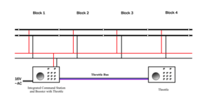
The Throttle Network connects throttles, boosters, and the command station together. It enables control of the layout.
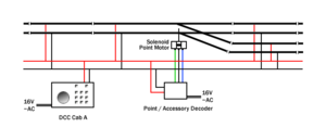
The Accessory bus is another DCC bus, usually fed by a dedicated booster, which supplies power and signals to accessory decoders. This allows DCC Accessory Decoders to be isolated from any drama which may be occurring on the track.
Auxiliary Buses may a simple method to supply power from a common source to a number of accessories. lighting effects and other layout elements.
Layout Wiring
Wiring Small Layouts
Small layouts, such as simple tail-chaser table-top layouts, can be wired in much the same way as a traditional analog layout. You should still read the various wiring articles, but fundamentally, if you can wire up an analog DC controller to some track, then you can wire up a DCC Starter Set to some track!
"Small" in this sense means small in size, small in complexity, and small in terms of the number of locomotives you intend to have on the layout. If you have multiple running lines, more than a handful of turnouts or want to have several locomotives in a motive power depot then you are really getting into "medium-size" territory.
Wiring Medium Size Layouts
If you've made it this far, you're probably embarking on a slightly larger project and you're looking for a bit more advice. You're not intending to build a great railroad empire but you want a fairly substantial layout with lots of operating potential and good running reliability.
- Read the Introduction to DCC and Starter Set articles
- Read all of the relevant wiring articles
As the layout gets larger you may want to consider additional options like Power Districts to better manage the layout. The throttle network will also be larger and more complex.
Wiring Large Layouts
- Main article: Wiring Large Layouts
Wiring a large permanent layout is definitely a challenge and not for the faint-hearted. You should research as much as possible before you get started.
Careful planning is a must, as you must consider Booster Districts, and other features such as Occupancy Detection may be necessary. The throttle network will also be more complex, and you may consider using radio throttles.
Wiring a Helix
A helix is a layout element which allows a train to move from one elevation to another. The basic helix is a circular ramp with multiple levels. The number of levels (or turns) is determined by the gain in elevation needed.
It would be very wasteful in terms of wire to simply follow the track. A 40" radius curve has a circumference of 21 feet, for each turn. A more economical method is to run the power bus vertically between the levels, and take feeders off at each level.
With the above example, two power buses (or more) can be run on opposite sides, with 3-foot feeders supplying the rails on either side of the power bus. Four feeders on a 21-foot track segment keeps them on the 6' maximum rule between feeders (This example is for HO Scale; other scales will be different). Additional sub power buses can also be employed, as well as additional feeders. Keep in mind that the longer the feeder, the heavier the wire should be.
Remember, there is no such thing as too many feeders.
Wiring Portable Layouts
Portable layouts, whether large or small, have their own set of issues.
If you can contribute additional ideas and content, please do.
Wiring Modular Layouts
There is no doubt that, when it comes to large layouts, the unchallenged champion is NTRAK. A typical NTRAK layout can consist of 30 to 50 four-foot modules. Larger regional gatherings can be over 100 modules. A national convention can be over 500 modules. The tried-and-true techniques they use for large layouts are an excellent starting point for anyone planning a large or modular layout.
Modular clubs will have published a set of standards they use in terms of wiring and connections. They will also standardize on a Digital Command Control system and its throttle bus.
Test Your Wiring
In this phase you will ensure that all of your wiring is working correctly. We will break this down into two parts, before and after turning the power on! First, the dry-run tests without the boosters connected to the DCC power bus:
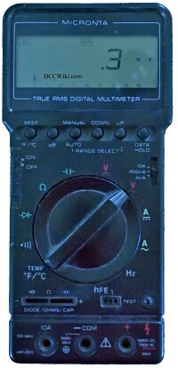
- Use a DMM or multimeter to check the resistance between each pair of bus wires, it should be "infinite" or in the megaohm range.
- Repeat this test for the accessory decoder buses.
- Check the resistance across each rail gap at the power district boundaries, again it should be very high. The power districts are supposed to be isolated from one another.
A simple trick is to use a continuity tester, be it a lamp, buzzer or a DMM with an audible alert. Connect the device across the two rails, and when it makes noise (or the lamp lights) you have a short somewhere. When the alarm stops, you have eliminated the problem.
After you have completed the dry-run tests you can start powering up individual boosters and testing them:
- Use a DMM, set to AC voltage, to test the voltage between the rails at various locations in the district.
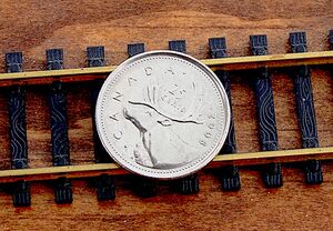
- Test booster cuts out when the track is shorted (e.g., using the Quarter Test).
- Test voltage drop under full load.
- Test live frogs are working.
- Test rolling stock does not cause short circuits.
- Test rolling stock crossing between power districts.
Videos About Wiring
DCC Wiring at Chadwick Model Railway
Building A Model Railroad - Wiring DC & DCC
See Also
- Wiring
- Electrical
- Throttle Network
- Boosters
- Turnouts
- Resources has links for publications which may be of assistance in layout planning and wiring.
