Programming Track
Summary: A track set aside for programming locomotives using Service Mode. It may or may not be part of the layout.
|
See the Video. |
A Programming Track is used to safely program Multifunction Decoders using Service Mode Programming. It is easier to have a portion of your layout's track to double as a programming track[1]. This minimizes handling of finely detailed locos on your layout and allows you to simply drive your loco to the programming section to read/change values of the decoder. It is best to have your programming track near the programming device (Command Station, SPROG, or Computer).
Reasons for the Program Track
While a programming track is primarily used to program decoders, it can also be used for an initial non-destructive function test on account of the output being current-limited to 250mA. Service Mode, which is used on the programming track, does not include an address in its data packet. Therefore, the decoder's address is not required to be known in order to program it.
The best reason for a Program Track is to prevent damage to a multifunction decoder.
- The programming output is current limited. Command stations which lack a program output usually include a resistor that is temporarily installed in series with the track circuit to limit the current. The resistor is not needed for normal operations. The NMRA Standard S-9.2.3 defines the programming track. It requires a separate, isolated track for programming which is both monitored and current limited. The multifunction decoder will acknowledge an instruction with an increased current draw of at least 60mA for 6ms, often by pulsing the motor.
- Some multifunction decoders have built-in short circuit protection, others do not. An incorrectly wired multifunction decoder can be destroyed when exposed to the track voltages used on a DCC layout.
- Any new, untried multifunction decoder install should never be placed on the layout, but on the programming track first. Should there be an error, the multifunction decoder will not be destroyed on the program track, due to the current limiting feature.
- For multifunction decoders with sound, an optional programming track booster can also be installed to feed the programming track. Not all systems require this, but many sound decoders cannot be programmed without one. See below for more on programming track boosters.
- It is too easy to accidentally program all the multifunction decoders on the layout with Service Mode programming.
The disadvantages of having a programming track:
- The dedicated programming output is usually only found on more sophisticated command stations
- A dedicated programming track must be constructed, either on your layout or the workbench.
- The locomotive/decoder combination to be configured must be moved or placed on the programming track.
- Motor operation and functions cannot be verified on a programming track. That must be done on the layout or a DCC powered test track
Of course, there are advantages to having a program track.
- Programming is done in a controlled manner, with low voltages and currents, eliminating the risk of damage possible when an incorrectly wired multifunction decoder is exposed to full DCC power on the mainline.
- The Program outputs are only active during programming.
- The Multifunction decoder's address is not required to configure it.
- Eliminates the possibility of programming all the motive power on the layout.
- CV values can be read and recorded manually or via software for easy record keeping
- A mistake made in the multifunction decoder's wiring will be forgiven. It will not cost you an expensive decoder.
Refer to NMRA S-9.2.3 for more information.
Service Mode Programming
The program track operates in what is known as Service Mode. Most command stations have a dedicated program track output, which switches on when in use. Operations Mode uses the main track output. On boosters which lack a program track output, the main track output is used for both modes. The danger is that when the booster switches to programming mode, Service Mode will write changes to all the decoders on the layout!
It is not possible to operate the vehicle or its functions on a program track. Service Mode provides power only during programming operations.
Track Connections
The PROGRAM output on a command station must never be connected to the TRACK output!
Independent Program Track
An easy solution to create a program track is to use an independent segment of track. This can be on the workbench or near the layout. The programming outputs of a command station are connected to the track for configuring a multifunction decoder. A toggle switch can be used (Break before Make type) to switch between Program and normal operation.
Using a second DCC command station dedicated to the program track makes programming convenient and easy. NCE Power Cab users could purchase additional components for the Power Cab to utilise it for the programming track, such as the Auto Switch. A SPROG or a Digitrax Zephyr is another option. Adding an interface for the computer will make a complete programming setup.
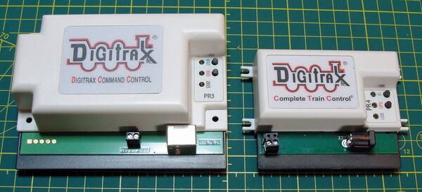
Devices such as the PR3/PR4 from Digitrax can be used, except they lack the ability to operate a vehicle.
Program Track on the Layout
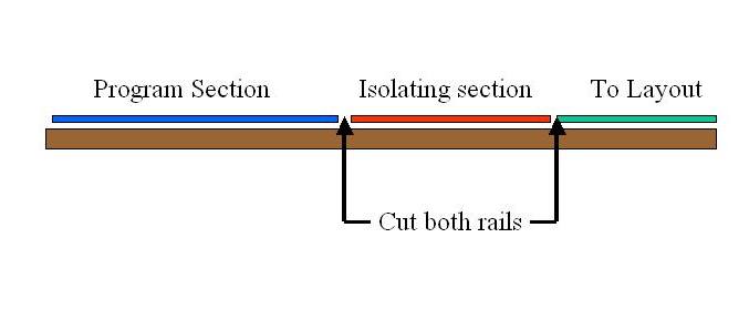
The biggest danger with a programming track on the layout is if a locomotive accidentally enters or exits the programming track and the switch is set for programming, the power pickups of the locomotive will short the two segments together. To prevent this, isolation of the programming track from the running track is necessary so that should a locomotive enter or exit the programming track during programming no harm is done. This is accomplished with a segment of track between the program track and the rest of the layout which is dead during programming operations. This segment should be longer than your longest locomotive for safety.
With the solution provided below, the worst that will happen is that the train will stop once the last power pickup enters the isolation area. Some multifunction decoders may creep forward during programming as a method of acknowledging the command was accepted, which can be an issue when using a method like DecoderPro to read or write multiple CVs, particularly when programming a sound decoder.
The addition of a center-off DPDT (break before make) toggle switch allows the use of programming and normal modes on the track for testing.
Isolating the Programming Track
To prevent a locomotive from accidentally shorting the program track create a section of track as shown below. The programming segment must be at least 50% longer than the longest locomotive, and the isolating segment must be longer than the longest locomotive. The longer the programming track segment is, the more useful it will be.
Remember, some locomotives creep forward during programming, so the longer the track, the better. Modern decoders have an acknowledgement feature built in. A program such as JRMI DecoderPro will send a new CV value to the multifunction decoder. If it works, the decoder will acknowledge this by briefly energizing the motor. This sudden draw in current can be detected by the command station. DecoderPro can by the same method read the CV values. It sends every possible value sequentially until the motor is energized. Thus, when programming or reading a large number of values the locomotive can creep forward quite a distance. Keep that in mind when planning the length of your programming track
Wiring the Programming Track
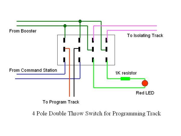
This is an example of how to connect a 4PDT (4 Pole, Double Throw) switch to the track. When the switch is in the normal position both sections of the track are connected to the layout and act as part of the layout. When the switch is the programming position, the program track (BROWN + BLACK wires) is connected to the programming device, while the isolating section (violet wires) is totally disconnected and the LED turns on. The red LED can be a signal near the track, or mounted between the track, or on the front of the facia, or both.
Why is a 4PDT Switch Used
Inevitably a mistake will occur, damaging the command station/booster. A 4PDT switch prevents accidental misconfiguration of the program track by only offering two possible states. Two DPDT switches offer 4 possibilities making a costly misconfiguration easy to accomplish.
The best choice of a 4PDT switch for your program track is a Center-Off version. This ensures that one circuit is completely disconnected prior to the new connection being established. Switches are available as "make before break" and "break before make". For this application, a break before make is essential, and a center-off version is the easiest way to make sure the switch breaks before making a connection. This avoids the possibility of momentarily connecting the booster output to the programming track output terminals.
Wiring the 4PDT Switch
- Booster
- Normal output to the track from the booster. In this mode, the program track and isolating section is connected directly to the booster output and functions as normal trackage.
- Command Station
- Output from the Command Station or Booster's dedicated Programming Track outputs, if equipped. If your command station lacks these connections, consult the manual for the proper wiring of a program track, which may require a series resistor to limit the current in this mode.
The left half of the switch selects the power source that connects to the programming track (BROWN + BLACK wires). When the switch is in the Normal position, the programming track segment is connected to the layout, and acts as part of the layout. When the switch is in the Program position, the program track output from the command station is connected to the programming segment.
The right half of the switch controls the isolating track (RED wires). In the Normal position, the isolating segment is connected to the main line. In Program position, the isolating segment is totally disconnected from the booster, and current flows through the LED.
The LED can be a signal near the track, or mounted between the rails, or on the front of the facia, or both. Note: The LED is optional and may or may not work depending on the DCC system used. Some DCC systems will shut down the main line when programming is active leaving the LED unpowered.
LED: Connect another general-purpose diode (not shown in the drawing) in series with the LED to protect the LED from being reverse biased. LEDs are not designed for high reverse voltages.
Check the switch operation with an ohmmeter to determine how the connections are made before wiring. They usually connect the terminals opposite the handle's position.
Programming Track Boosters
| Programming Track Booster | ||
|---|---|---|
| Model | Booster Needed? | Notes |
| Digitrax DB Series | No | No connections for program track |
| Digitrax DCS Series | Yes | May not be required with newer models, check manual |
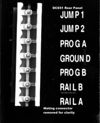
| Digitrax Zephyr (DCS50, DCS51) | Yes | Not required if using Blast Mode[2] |
| Lenz LZV100 | Yes | Firmware greater than Version 3.6 should not require a booster |
| NCE Power Cab | No | NCE does not recommend their use. |
| NCE Power Pro / Power House | Yes | See Power Pro section below |
| Zimo | No | A program track booster may damage the command station. |
This usually is an issue with Sound equipped Decoders. Programming a vehicle with an energy storage device installed may also benefit from usage of a program track booster. It will work with non-sound decoders as well.
If attempts to program a decoder result in unwanted changes or a non-responsive decoder, a Programming Track Booster may be needed to overcome these issues. It is connected between the command station/booster and the programming track, as per the manufacturer's instructions. Sound decoders arrived after the NMRA defined the DCC standard, so the basic requirements for programming a decoder, while adequate, often do not work with sound equipped decoders which require more current during programming. DCC Systems designed and manufactured in recent years, and recent decoder models, often do not require a program track booster for successful programming.
This device will often be recommended by the decoder manufacturer when there are difficulties programming the decoder. They are available from your dealer. If in doubt, ask your dealer, the decoder or your DCC System's manufacturer. They will advise if you need a program track booster or not.
A Programming Track Booster serves to make programming more reliable, and may also incorporate short circuit protection and basic diagnostics. It may also provide feedback to aid in troubleshooting a problematic decoder.
NOTE: This device will not solve problems created by the user during installation. Its sole purpose is to make the process of programming more reliable. The device may not be needed, depending on the DCC brand/model chosen by the user. As always, consult the decoder and Program Track Booster manufacturer, or your dealer, to determine if this device would help.
Notes
Programming Track Boosters and Power Cab
- DO NOT connect a programming track booster of any kind to an NCE Power Cab. The programming track mode of the Power Cab is a newer design that incorporates the ability to program sound equipped decoders.
NCE Auto-Switch
The NCE Auto-Switch detects Service Mode packets, then switches its output from track power to program track. It has one input from a booster, such NCE's Power Cab, and two outputs.
It works with boosters which lack a dedicated output for the programming track. Also suitable for use with Digitrax's Empire Builder, Big Boy or Challenger sets. Program on Main (Ops Mode) does not activate the program track. It eliminates the possibility of Service Mode programming mode being activated and programming everything on the layout. Service Mode commands are only sent to the program track.
If your booster does not have programming capability, such as the NCE Smart Booster, this device will not work with it.
NCE Power Pro Modification
The NCE Power Pro can be modified to increase the track current available during programming.
The outputs are protected from a current overload using small lamps to limit the current. Adding two additional lamps in parallel with the existing ones will double the current.
See Instructions here for more details on this and other modifications.
Digitrax DCS240 Command Station
The program track output in the new DCS240 and DCS240+ is improved and does not require a programming track booster. Users report being able to successfully configure older Soundtraxx Tsunami decoders which previously required the PTB-100 with their DCS100 command station.
PowerPax
The PowerPax DCC Programming Booster by DCC Specialties is an older design which may not work with all decoders and command stations. There are timing differences which may be an issue as well. Soundtraxx's PTB-100 was designed when programming sound decoders became an issue, and addresses the timing problems.
Soundtraxx Tsunami2 and Econami Series DCC Decoders
The Sountraxx Tsunami2 (TSU-2) and Econami series of decoders do not require a programming track booster. Users have reported that attempting to program the TSU-2 or Econami decoders with a PowerPax gives erratic results.
Previous Tsunami sound decoders required a program track booster.
QSI Decoders
A programming track with booster is recommended for best results when programming QSI decoders. A Digitrax PR3 or PR4 will also work.
Videos
Wiring a Program Track
Building a Standalone Portable Program Track
Further Reading
- Decoder Programming - Additional information about programming decoders
- Track wiring - Track wiring
- PTB-100 - Programming Track Booster by Soundtraxx.
- Decoder Tester - Apparatus for testing and programming decoders.


