Train Detection
Summary: Various methods are available for detecting the location of locomotives and rolling stock on a model railroad.
|
See the Video. |
Train Detection Overview
| Basic wiring |
|
| Track wiring |
|
Train Detection can be divided into three broad categories by location accuracy:
- Block detection - whether a train is located somewhere on a particular section of track, or block.
- Location detection - whether a train is located at a specific point on the layout.
- Proximity detection - whether a train is located at or near a point on the layout.
It can also be categorized by the type of information reported:
- General - any locomotive or piece of rolling stock is reported.
- Classifying - only locomotives or only specially-fitted locomotives or pieces of rolling stock are reported.
- Identifying - the specific ID of a suitably-equipped locomotive or piece of rolling stock is reported.
Lastly, it can be categorized by the technology used:
- Optical - detectors that use Infra-Red or visible light.
- Conductive - detectors sensitive to the track supply current or voltage.
- Proximity - detectors sensitive to objects nearby.
General Detection
We'll start off with the various generic detection methods, i.e. methods that detect all locomotives and/or all pieces of rolling stock:
Optical Detection
Many references can be found to various designs for optical detection, making use of Light Dependent Resistors (LDR) or Photo Transistors and IR detector pairs. Each has its own challenges and applications depending on the track layout, detection requirements, sensitivity and expense.
Advantages:
- Independent of the operational control system, i.e. DC or DCC control and power on the track.
- Can detect a small area of the block, and if paired, can detect direction of occupancy
- Does not need any resistors or modifications to rolling stock.
Disadvantages
- Can be more complicated to align detector pairs.
- In the case of LDRs can be sensitive to ambient light and require careful shielding.
- Can look between rolling stock and appear to be unoccupied. This can be countered by diagonal placement.
Light Dependent Resistor
- Probably the most common detector used in the past was the LDR or Light Dependent Resistor. This is an electronic device which changes its resistance in proportion to the amount of light to which it is exposed.
- A detection circuit deploying a LDR would typically use an incandescent light or LED on one side of the track, and an LDR on the other and detect the interruption of light impacting the LDR, as a locomotive or stock moving or standing on the track in front of the detector.
Advantages:
- Has a natural hysteresis due to its lower switching speed.
Disadvantages
- Can be more complicated to align detector pairs.
- Sensitive to ambient light and requires careful shielding.
Photo Transistors and IR Detector Pairs
- A more current and popular optical detection solution these days is the IR Detector pair. This circuit makes use of a matched Infrared Transmitter and Receiver spanning the track to detect occupancy.
Advantages:
- Longer range, can be designed to detect over long distances, even down the track.
- Not as sensitive to ambient light thus more reliable that LDRs.
Disadvantages
- Hysteresis must be designed into the detection circuit to cater for the quick switching speed of an IR photo detector, otherwise errors can be detected.
Conductive Detection
Many references can be found to various designs for conductive detection, by the detection of any current being consumed on the track block as an indication that the block is occupied. This is the most common form of block detection used on DCC layouts.
Advantages:
- Independent of the ambient lighting environment around the track.
- Detects an entire block's occupancy and can detect direction of occupancy (Block to Block)
- Detects any rolling stock in the block that is drawing electrical current.
Disadvantages
- Circuit is dependent of the operational control system, i.e. Direct Current or Digital Command Control, and power on the track, and is more complicated to design for DCC.
- Track must be broken into electrically isolated blocks.
- Requires the addition of a resistor on the insulated axles of rolling stock (like Guard Vans (caboose)) if they are to be detected on the block, which in turn draws more current overall.
Voltage Drop
- The simplest form of circuit uses a Diode (two Back-to-Back Diodes for DCC) in the power feed to the block, and measures the Voltage Drop (Vdrop) across the diode to detect current flowing across the tracks, and thus occupancy. It would be similar to the diode arrangements used for Asymmetrical DCC.
Advantages:
- Simple circuit to design and low cost
Disadvantages
- Diode causes a voltage drop to the track.
- Diode must be able to accommodate short circuit currents
- Circuit design is complicated for DCC and ideally track power and detection feedback should be electrically isolated
If one diode fails, it could break the circuit with the track, rendering that section dead. Only half the DCC signal would be present. This could also trigger the decoder to switch to analog mode and cause the locomotive to accelerate out of control.
Some circuits require the use of resistor wheel sets. A resistor is affixed to the axle, and connected to each wheel. The current flowing though the resistor triggers the detector.
Resistor wheel sets can be made yourself, or purchased from your hobby shop. They add cost to the system, as it may be necessary to add a pair to the car for reliable operation. A typical application would be the caboose/van.
Current Transformer (CT)
- Design uses the conductor that feeds the power to the track, passing through a Current Transformer (CT) and a detection circuit to measure the current generated in the CT. Design needs to cater for the DCC signal noise but works for both DC and DCC.
Advantages:
- Does not cause any voltage drop to the track.
- Isolated from the track voltage and current.
- Increased immunity to noise compared to the Voltage Drop circuit.
- Additional turns of the conductor through the CT can be used to increase sensitivity
Disadvantages
- Circuit is more expensive than Voltage Drop circuit
- Must be rated for, but more tolerant of short circuit current.
Hall Effect Current Sensor
- Design uses the conductor that feeds the power to the track, passing over/through a Hall Effect sensor (HE) and a detection circuit to measure the sensor response. Design needs to cater for the DCC signal noise, but works for both DC and DCC.
Advantages:
- Does not cause any voltage drop to the track.
- Isolated from the track voltage and current.
- More sensitivity to current passing through the tracks.
Disadvantages
- Circuit is more expensive than Voltage Drop circuit
- Must be rated for short circuit current but more tolerant.
Can also be used in some cases to detect the Magnetic Field generated by the Motor in the Locomotive as it passes over the sensor, embedded between the tracks!
Proximity Detection (Metallic or Ultrasonic)
Design uses a Proximity Sensor (PS) to detect a metallic object passing within a short distance of the sensor. The sensor can be embedded between the tracks and detect the Locomotive or Rolling stock passing over it.
Advantages:
- Isolated from the track power.
- Detects a larger area with less errors.
Disadvantages
- Circuit is much more expensive than any of the others.
- Metallic Proximity Sensor will only detect the Locomotive, not plastic rolling stock.
- Ultrasonic sensors are prone to noise from other occupied tracks. i.e. Not useful in a yard.
Classifying Methods
These methods can distinguish between different types of rolling stock.
Conductive Detection
As described above, conductive detection can be made to detect specific items of rolling stock if they are fitted with resistive axles. Items with normal axles will be "invisible" to the detector.
Reed Sensors
This is Roco's and Fleischmann's preferred method of train detection, and they manufacture all the necessary components. Design uses reed switches placed inside or between track sleepers (ties) triggered by magnets on the train's undercarriage. Same idea used in burglar alarms to detect windows or doors opening. "Advantages:"
- Not affected by light
- Cheap and simple to install
- Reed switches are available at electronics retailers
- A special train can be exempted from triggering things by not adding a magnet
"Disadvantages:"
- Requires small magnets to be attached to underside of locomotives (available from Roco and Fleischmann)
- Reed switches will melt if large currents are passed through them; requiring a special module or a relay
Identification Methods
Lastly, we'll briefly touch on methods that can identify the exact locomotive or item of rolling stock.
Bidirectional Communication
This is a DCC-specific method of block detection where mobile decoders transmit their identity using Transponding or RailCom. If the track is divided into blocks, a locomotive can be detected and identified by the receiver connected to that section of track.
- In this example a block could be a power district or a power district divided into smaller units.
Radio Frequency IDentification
As known as Near Field Detection.
With lower cost RFID (Radio Frequency Identification) components and tags becoming available, this technology could have implications in the future. Tags which can be mounted on a truck frame are available for less than US $1.50. This tag is basically a very large antenna and a tiny chip. Energy from the reader provides the power for the chip, which then responds to the query. Even the cheapest RFID tags can store a unique 90- or 128-bit number. Compare this to a barcode and its 33 bits or less. Standard RFID tags can store up to 2kb, with some having as much as 8kb for specialised tracking purposes.
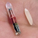
Using a small RFID tag installed in rolling stock or motive power, it is possible to not only to detect the presence of a train, but the motive power and the manifest. Mounting a small grain of rice RFID tag on the underside of a truck frame has been found to be effective.
As the train passes an RFID reader hidden beneath the track or in the scenery (which includes buildings), every tag is read and transmitted to a connected computer. The software can then determine which cars have passed the detector. The software can then determine where that car is. This is possible as every tag has a unique number.
A DCC application would be able to link the locomotive's RFID to a database containing all the details of it, included installed decoder, etc. It could even be used to link it to a specific set of CVs. All the user would need to do is wave the detector near the locomotive and the RFID tags and the computer do the rest.
If all the rolling stock is tagged it would be possible to know, for example, when a car leaves or enters a yard or passes a station. If operations software allows it, it would know if the car is in the yard or not, and be able to verify the consist as it passes a reader.
It could also be used to maintain a club database with information on the model's ownership.
There is an email list on Groups.IO dedicated to the application of RFID in model railroading.
Videos
- Main article: Train Detection/RFID Videos
A few videos demonstrating the technology.
Types of RFID Tags
- Active Reader / Active Tag
- Active Reader / Passive Tag
- Passive Reader / Active Tag
For model railroading the active reader coupled with a passive tag is the best solution. The reader emits RF pulses, and the tag (when in range) responds. The tags require no external power, they are powered by the RF pulses from the reader. Most tags used in model railroad applications are the 125kHz variety. Lower frequencies require the tag to be closer to the reader, which has a much larger antenna.
RFID works well at speeds seen in the yard, so mainline operations may be unreliable. They will work on metal bodies. If needed, a 100thou shim between the tag and the body can reduce interference enough for proper operation. There are few issues surrounding their installation on a locomotive.
RFID Readers
There are a number of readers based around Arduino and Raspberry PI devices. They can use Wi-Fi, USB or Ethernet for communications. The readers are sensitive enough to read tags mounted on truck frames, while being selective and ignoring tags passing on an adjacent track.
Remember, the tags must be compatible with the reader technology.
JMRI Support
JMRI supports the following:
- CORE-ID / ID-Innovations
- Olimex MOD-RFID125
- Olimex MOD-RFID1356MIFARE
- Parallax
The only concentrator that JMRI supports at this time is the one by MERG.
For further details see Hardware Support: RFID Readers
Commercial Products
A number of suppliers exist for RFID tags and readers
- Parallax is a supplier of RFID components.
- Grand idea Studio designer of the reader sold by Parallax.
Model Railroad Specific
- CTI Electronics offers an RFID system for their software
- Model Railroad Control Systems has a full range of RFID components and tags. They also offer a complete starter set, with a RaspberryPI based RFID server, a reader, and 10 tags to get you started.
- TrainTraxx offers a full suite of hardware and software for RFID. Individual parts or complete starter kits. Their software can maintain your inventory and be available on your smart phone. Hardware is JMRI compatible.
- StaRFIshrail a complete multiple RFID system designed specifically for model railroads. Works with N, OO/HO and O gauges. JMRI, Rocrail and CBUS interfaces.
Commercial Detection Systems
Under Construction!
- Main article: Train Detection Systems
See Also
Block detection Circuit for a low-cost occupancy detector
The Model Railway Show (podcast) has some pictures of an RFID setup on their Flickr Page. There is more discussion on Episode 46 of the podcast.
Presentation on RFID: RFID In Model Railroading
RFID
Model Railroader published an article on RFID:
RFID for Model Railroad Operations
Authors: Chris Drome, Seth Neumann
Model Railroader December 2014
Prototype
“AEI (Automatic Equipment Identification) technology is 40 years old and tells us where our shipment was. What we need is a technology that tells us where our shipment is, and a more realistic estimate of when the customer can expect to receive it.” – a railroad member of RailPulse
Real-Time Tracking: What Are We Waiting For?
The Forgotten Story of Kartrak: The First Barcode
A video on the Kartrak system, a series of coloured bars on the side of freight cars to identify them as they passed a reader.
ACI Colour Codes
The ACI Label is 10.5" wide by 22" high, with 13 stripes 6" by 1", using the colours red, blue, silver and black. The camera sees the silver band as either red or blue, and black is seen as neither red nor blue for processing purposes. Each stripe represents a deciml value, and is divided into an upper and lower half. The label is read from bottom to top.
The preferred location for the label was between 6 and 9.5' above the railhead, the optimum being about 7 feet.
The system was abandoned when it was determined that it wasn't reliable due to dirt and fading.
| ACI Colour Codes | ||
|---|---|---|
| DCCWiki.com | ||
| Symbol | First Colour (Bottom) |
Second Colour (Top) |
| Start* | Red | Blue |
| Stop* | Blue | Red |
| 0 | Blue | Silver |
| 1 | Silver | Silver |
| 2 | Silver | Red |
| 3 | Red | Black |
| 4 | Red | Red |
| 5 | Blue | Black |
| 6 | Silver | Blue |
| 7 | Red | Siver |
| 8 | Silver | Black |
| 9 | Blue | Blue |
| 10** | Blue | Red |
| * | Each colour occupies the entire 6" wide segment but the upper colour will occupy first four inches on the left, and the lower colour the last four inches on the right | |
| ** | Parity bits only | |
| Automatic Car Identification | ||||
|---|---|---|---|---|
| DCCWiki.com | ||||
| Meaning of Stripe Positions | Equipment Codes | |||
| Location | Purpose | Value | ||
| 13 (Topmost Position) | Parity | 0 | Railroad and Private Owner cars | |
| 12 | Stop | 1 | D0 | |
| 11 | Car Number | 2 | Trailer | |
| 10 | 3 | Trailer Expansion | ||
| 9 | 4 | Container | ||
| 8 | 5 | Container Expansion | ||
| 7 | 6 | Work Equipment | ||
| 6 | 7 | Passenger car | ||
| 5 | Owner | 8 | Caboose | |
| 4 | 9 | Locomotive | ||
| 3 | ||||
| 2 | Equipment Code | |||
| 1 (Bottom) | Start | |||
For more information see the NMRA Bulletin, January 1977.


