Accessory Decoder
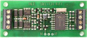
Summary: This type of decoder is normally mounted under the benchwork or alongside the track for control of accessories from a throttle, such as turnout motors. Like multifunction decoders, accessory decoders act on DCC commands from a throttle.
What is an Accessory Decoder?
- Parent article: Decoder
Accessory decoders can be used to control turnouts, structure lights, scene lighting, animation, and signalling.
An NMRA compliant accessory decoder (sometimes called a stationary decoder) is intended to be controlled by the same DCC power used for multifunction decoders or via the throttle bus. From a DCC perspective, the difference is address partitioning and types of outputs. Whereas a multifunction decoder drives motor with all its speed controls, momentum, braking etc., an accessory decoder is only concerned with on/off (or "forwards/backwards") functions for accessories. Accessory decoders intended for signalling applications may have additional states for that purpose.
Accessory Decoder Addressing
Accessory Decoders have the address partition of 128 to 191. They can have a 9- or 11-bit address. Extended Accessory Decoder Addresses use the 11-bit address.
Accessory decoders that have extended addressing will not interfere with multifunction decoders. For more, see Will accessory decoders having extended addresses interfere with multifunction decoders?
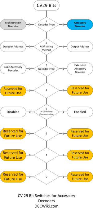
Also see Configuration Variable CV29 and CV articles for more information on Accessory Decoder Configuration.
Accessory Decoders use one of two addressing methods:
- Decoder Address
- Output Address
Applications
A primary use of accessory decoders is controlling turnout motors so many are specifically designed with this purpose in mind. There are two common types of turnout motor; solenoid (e.g., Peco Point Motors) and stall motors (e.g., Tortoise Switch Machines) and each requires a different kind of electrical drive. The solenoid type requires a short but powerful pulse of current to snap the turnout from one way to the other whereas the stall type require a constant but low current to drive a geared motor slowly from one side to the other. They are called stall type because they will stall when they reach the mechanical limit and the stall current can be maintained indefinitely to hold the switch blades in position. The solenoid type will be destroyed if current flow was not cut off.
Solenoid motors are best driven by a capacitive discharge device that uses the energy stored in a large capacitor to supply a short, powerful pulse to the electromagnet without the risk of overheating it. Some accessory decoders have this capacitor built in; others simply allow you to set the pulse duration. Solenoid types can be 2-wire or 3-wire; the 2-wire ones use a single coil with the polarity of the DC voltage determining the direction of throw whereas the 3-wire ones use two coils, one for each direction.
Regardless of the motor type, a pair of decoder outputs is required for all turnout motors, one to set the primary route and one to set the diverging route. This output pair has a single DCC Accessory Address.
Another common use for accessory decoders is signaling; either electromechanically operated semaphore arms or colour light signals. Again, standard practice is to use a pair of decoder outputs to drive a single signal. For Multi Aspect Signaling, where there are more than two lights involved, things get a bit more complicated.
An accessory decoder can be used to control any other simple on/off function such as structure lighting, animation effects, crossing gates, water pumps, etc. Also, there are no DCC police to say you can't put a accessory decoder into a piece of rolling stock. For example, you could install a small one in a dining car to control the lighting. Decoders made for this purpose are usually called function only decoders
Output Types
To summarize, this table shows the various types available:
| Type | Description | Example Uses |
|---|---|---|
| Momentary Pair | Pulse output | Solenoid or snap type turnout motors |
| Solenoid type semaphore signals | ||
| Constant Pair | Constant bidirectional output | Slow motion stall-type turnout motors |
| 2-Aspect colour signals | ||
| Single | On/off type output | Structure lighting |
Power Sources
DCC Track Power
An accessory decoder may take its power from the track supply or another separate DCC supply bus. This is obviously the only method available if the decoder is mounted inside a piece of rolling stock.
External Power Supply
An accessory decoder can be powered from a completely separate power source even while receiving its control signals from the DCC track power or other DCC supply bus. This has several advantages as described below (see Avoid Connecting to Rails).
Control Types
To be considered DCC Compatible an accessory decoder must be able to receive control signals from a DCC source, regardless of where it is actually drawing its power from, such as the track.
Many accessory decoders support dual control paths, using a DCC bus and/or throttle networks.
Some accessory decoders only accept control signals from proprietary throttle networks, these are not really DCC and are unlikely to be compatible with any other manufacturer's equipment.
Avoid Connecting to Rails
Most accessory decoders can be connected directly to the track for power and to receive DCC commands (telling them what to do). However:
- It should be noted that it is not recommended to connect accessory decoders directly to the rails if your DCC system allows for another method. The reasoning is that the decoders will draw power that could otherwise be used for locomotives and other rolling stock. DCC power is very expensive when compared to a traditional power supply.
- A more important reason: In the event of a short on the line (often the result of running a turnout set against you) there will be no power to the stationary decoder controlling the offending turnout, therefore you will have to move the locomotive by hand to clear the short.
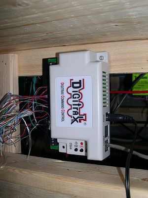
- If your system allows for an external power source, other than the rails, utilize this. If your system and accessory decoder allows for an external method of receiving commands, this should be utilized as well. For example, a Digitrax accessory decoder can receive its commands, and send decoder status information back to the command station, through the throttle network (LocoNet in Digitrax's case).
If you simply must use track power style power distribution with your accessory decoders, use power managing device to create an isolated accessory decoder power bus independent of track power. Another solution is a separate bus driven by a dedicated booster exclusively for use by accessory decoders.
Using the track power for commands instead of a throttle network or dedicated bus results in an endless loop taking place. A locomotive shorting out a turnout shuts down the track bus. The accessory decoder cannot clear the short by realigning the switch rails if it gets its commands from the track as there is no DCC signal. The track bus is reenergized, the power is cut, and the cycle continues...
Using a separate bus for device commands eliminates that problem, as the accessory decoders will get their commands independently from the track bus.
Further Reading
- Accessory Decoder Addressing
- Multifunction Decoder - A decoder mounted in vehicle, such as locomotives or rolling stock.
- Function Decoder, used to provide additional functions or functions in rolling stock.
- Signal Decoder - Accessory decoders suited to controlling signals.
- Other DCC Equipment


