Cab Bus
Throttle Network:
Cab BusSummary: The Cab Bus is NCE's Throttle Network protocol. It is a polled network which supports up to 63 addresses. In addition to NCE, Wangrow's System One and PSI's DYNATROL also employed the Cab Bus protocol. A subset of the Cab Bus is the Control Bus, used to link boosters together.
| See more Throttle Networks | |
|---|---|
| General information | |
| Common Name | |
| Used by | NCE, Wangrow, Dynatrol |
| Reference material URL | Manual Link |
| Has computer interface | Other |
| Year Released | |
| Year EOL | |
| Predecessor | |
| Successor | |
| Network Details | |
| Network Type | Polled |
| Number Of Max Devices | 63 |
| Is open source | No |
History
The Cab Bus is a serial communications protocol developed by NCE and used by Wangrow Electronics' SystemOne. Other DCC manufacturers adopted the Cab Bus as well, such as PSI's DYNATROL
|
See the Video. |
Description
In addition to NCE, Wangrow's System One and PSI's DYNATROL also employed the Cab Bus protocol. There are two physical forms of the Cab Bus wiring. Cab bus connections between the throttle and the command station or throttle network use a 6P4C or 6P6C RJ connector, which can use four or six conductors in the cable. The 6P6C is specifically for the Power Cab.
NCE employs a Control Bus to connect boosters to the command station. The Control bus uses a four-wire cable.
Systems Employing the Cab Bus
- North Coast Engineering (NCE)
- Wangrow Electronics Inc.
- PSI Dynatrol Digital
Overview
The Cab Bus is polled network. Devices on the network do not speak until spoken to. The command station software controls the polling frequency and sequence. Cabs are not polled in numerical order. If a cab does not respond to a ping after several attempts, the command station will stop pinging that address. The command station will periodically ping all addresses, to discover new devices or acknowledge dormant throttles. It will ping addresses on a random basis to speed up operations when more than 30 cabs are on the bus. For faster response active cabs are polled more often than inactive cabs.
The Cab Bus connects up to 63 Hand-Held Cab Controllers to the Command Station. Data on the bus runs at 9600 bps, eight data bits, no parity, two stop bits and meets RS-485 specifications.
The limitations of the polled network are the number of devices (nodes) on the network, and speed. As more devices are added, their response time increases. At some point the electrical limits of the network will be reached, or a software-imposed limit. This determines the total number of nodes which can be connected to the network. Optimal polling cycles are determined by the hardware's speed and bandwidth.
The Cab Bus system is a polled system. Devices are continually in receive mode unless specifically addressed by the command station, at which time the command station relinquishes the bus to allow the device to respond. When throttles are polled, they respond by transmitting any change in status.
The bus should be a continuous daisy chain without "branches" of any significant length (longer than 8 feet). The RS-485 Specifications suggest data rates up to 10Mbits/sec are possible, or at lower speeds for distances up to 1200 m. As a rule, a 50 m cable should allow signalling rates up to 2Mbits/s. NCE suggests no longer than 300 m (1000ft) is acceptable, with branches not longer than 6 m.
Cab Bus
The Cab Bus can connect up to 63 Cabs to the command station.
Data on the bus is 8N2 (eight bits, no parity, 2 stop bits) following the RS-485 specification.
The cabs are in listen mode until they are specifically addressed by the command station (polled), at which time control of the bus is passed to the cab. All data sent from the cab is required to have bit 7 set to 1. A "ping" has bit 6 equalling 0, all other commands or data will have bit 6 set to 1
Operation
The cabs are continuously polled (pinged) for any change in status. When polled, the cab will reply with either a 2-byte response indicating a button press (first byte) then the second byte with speed information, or with a five-byte message indicating the device address (2 bytes), then the operation (2 bytes) followed by a one byte XOR checksum.
The cab will begin transmitting approximately 780 µS after receiving the last stop bit from the command station.
Cab Addressing
Cab addresses 0 and 1 are reserved. Cab 0 is the broadcast address of the command station. Cab 1 is reserved for future applications.
Cab Address 2
This Cab Address is special. Cabs on other addresses can have their capabilities limited, such as preventing the ability to change CVs or use the Momentum key[1]. The Cab on address 2 is the master cab, and retains all its functionality.
Normal Operation
- Command station pings an address
- Cab answers
- If the cab has nothing to send, it does not have to respond.
- If command station has data for the cab, it is sent after the cab finishes transmitting
- Repeat process by pinging the next address
If a cab does not respond for several pings, it may be dropped from the queue for inactivity. Its address will then be pinged periodically until it responds to a ping.
Response Time
Under normal circumstances, with 10 cabs in operation, a cab will be pinged about 23 times a second.
To poll all 63 addresses, the frequency per cab will be 3 to 4 pings/second, assuming 63 cabs in use and all are responding with a simple 2-byte response. Most NCE users will never experience this level of performance.
Discovery
The command station polls the cab bus at regular intervals. In addition to the known addresses, it generates a random address during each polling sequence. This is done to discover any new devices which have been added to the Cab Bus.
Once an address is on the polling list, it stays there. During large or long operating sessions, restarting the system when time permits will clear the list of device addresses, removing any inactive devices and allowing the command station to create a new list with active devices. This is important if cabs are being added and removed from the cab bus during the session, as polling addresses which are inactive add unnecessary overhead and bus performance suffers.
Additional Information
The Cab Bus is a polled network, as opposed to a CSMA/CD network such as Digitrax's LocoNet. As the network expands, throughput decreases as more devices are polled.
Under polling, the device must silently wait until addressed, whether or not it has a message to send. A CSMA/CD network does the opposite, a device sends a message without being asked and will continue sending the message until it determines it was successful.
Wireless Interference
An unfortunate consequence of the CAB Bus's polling nature is the constant messaging traffic to all cabs on the bus. With wireless throttles, this generates a lot of radio traffic. Which is not a problem in a home or club setting. It becomes a hurdle with nearby layouts using wireless throttles in an exhibition environment. The volume of radio traffic the Cab Bus generates will swamp nearby receivers, as they are all on the same band.
Cab Addresses
- Main article: Cab Bus Addresses
Cab Bus Wiring

Proper wiring is important. While the CAB Bus may work, at some point in the future when additional devices are added bus problems will occur. Spending extra time and using a little more wire will avoid those problems in the future. The underlying electrical issues were always there, it only takes a few more devices on the bus to bring them to the surface.
As mentioned above, the maximum length of the Cab Bus is 500' in a continuous run (daisy chain), any branches off the bus should be no more than 8 feet long. The Cab Bus and its throttle panels should be arranged in a daisy chain fashion, one feeding the next. Attempting to save wire by using stubs off the main bus to feed throttle panels will result in issues. If stubs are needed, they must be very short, no longer than the length of a coiled throttle cable.
It is important to arrange and wire the Cab Bus in a linear fashion. NCE does not recommend splitting the Cab Bus nor the use of stubs. As this is a serial protocol, it is meant to go point to point. It cannot be wired as a star, nor should it form a closed loop.
Cab Bus Power Requirements
NCE recommends the addition of a Cab Bus power source every 40 feet, dependant on the number of cabs installed/in use.
As more Cabs are added to the bus, more power will be required. Additional power supplies can be added, UTP panels have the facility to connect using a 3.5mm barrel plug. See the manual for the cab bus panel for additional details.
If the number of cabs in use overload the command station, the system can become unstable and possibly crash.
Control Bus
This is used to connect between boosters and the command station. It uses a 4P4C RJ-H plug and socket, carries a low level DCC signal for the booster.
Boosters have two connections to allow pass-through to additional boosters.
Rapid flashing of the status light indicates the control bus isn't connected to the booster. It will do this when the programming track is active.
UTP Panels
The UTP has four connections, and can be used as a three-way splitter to split the cab bus into three segments. See the NCE website for details. There is a newer version available which allows for the use of CAT5 cabling between UTPs.
Cab Bus Panel
Similar to the UTP, but only four connections, two for the cab bus and the remaining pair are for cabs.
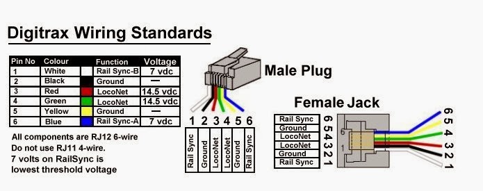
Digitrax UP5
The Digitrax UP5 is not compatible with the cab bus without modifications.
NCE Cab Bus Cables

Connectors
- Main article: Cab Bus Connectors
The NCE Bus connections are as follows:
- Control Bus: RJ-H / RJ9 4P4C, four wire cable between boosters and command station.
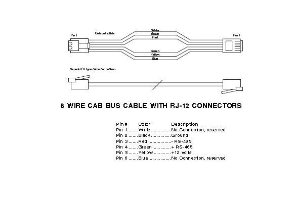
- Cab Bus: RJ12, 6P4C. Cabs may be directly connected to the command station. This bus connects the command station to throttle panels (UTPs) around the layout.
Power Cab Cable
The Power Cab comes with two Cab Bus cables:
- A flat six conductor cable for use in its Power Cab mode
- A coiled, four conductor cable for use in its Pro Cab Mode, when connected to an external command station.[2]
The Power Cab comes with a custom RJ12 6P6C cable. Do not attempt to make your own. Replacements are available from NCE. Third party cables lack the heavy gauge conductors to carry the track current.
Cables
| Cab Bus Cables | DCCWiki.com | |||
|---|---|---|---|---|
| Cable | RJ Connector | Description | Purpose | Notes |
| Control Bus | RJH/RJ9 4P4C | Four wire cable | Control bus between Boosters and Command Stations | Max length: 300 ft. / 91m |
| Cab Bus | RJ12, 6P4C | Four wire flat or coiled cable | Connect Cabs to Cab Bus[3] | Only 4 connections in plug are used |
| Cab Bus | RJ12, 6P6C | Flat six wire cable | Power Cab to layout | Carries power, specifically designed for the Power Cab[4] |
For additional examples, such as interfacing with Lenz or Digitrax boosters, see the NCE System Technical Manual.
Additional Cab Bus Resources
- MERG: Protocol.Zip file.
- NCE DCC Cables Explained for more information on Cab Bus cables, and how to order a new one for your Power Cab.
- NCE System Technical Manual
- NCE Cab Bus
- Electronics: Cab Throttle
- NCE Default Polling Lists
RS-485 Throughput
Speed in bit/s multiplied by the length in metres should not exceed 108. Thus a 50-meter cable should not signal faster than 2 Mbit/s.
50 × 2M = 100 × 1,000,000 = 100,000,000 or 108 (1006)
- Therefore, 300 m cable = 1006 ÷ 300 ≈ 0.3 Mbits/sec. (100,000,000 ÷ 0.33 × 1,000,000 ≈ 333 m)
NCE Helpdesk
There are a number of useful articles on the Cab Bus on the NCE website:
- File:Cab bus protocol.pdf
- LocoNet Wiring
- Digitrac NCE cab bus cross reference
- RJ12 Wiring Diagram
- NCE-DCC: Cables Explained
- Cab Ids 101
Videos
Cab Bus FAQs
- Cab Bus Addresses
- Cab Bus Addresses, Power Cab
- Cab Bus Connectors
- Difference between NCE Pro Cab and Power Cab
- How to Determine Cab06 Firmware Version
- NCE Firmware Versions
- NCE Radio Base Station Issues
- NCE USB and Power Cab
- Power Cab Overcurrent Protection
- Power Cab cannot Communicate with Expansion Devices
- What is the Cab Bus
See Also
Articles Referencing this Page
- 5240001
- 5240003
- 5240005
- 5240008
- 5240025
- 5240027
- 5240028
- 5240035
- 5240036
- 5240045
- 5240050
- 5240051
- 5240223
- ACCU-LITES
- AIU-01
- ↑ The Momentum key makes changes to CVs 3 & 4 using Ops Mode Programming.
- ↑ Always use this cable for Pro Cab (throttle only) mode to avoid adding interference to the Cab Bus.
- ↑ Pro Cab cables require the four center conductors for proper operation.
- ↑ Using a cable other than that supplied by NCE voids the warranty.